Level Measurement: In industry, liquids such as water, chemicals, and solvents are used in various processes. The amount of such liquid stored can be found by measuring level of the liquid in a container or vessel. Level sensors detect the level of substances like liquids, slurries, granular materials, and powders.
A Capacitance switch designed for single point level detection in both solids and liquids.
Capacitance Level Switch Calibration
Every material has a relative permittivity or dielectric constant. A basic capacitance switch uses this dielectric constant to complete a capacitance circuit between a sensor and a reference. The presence of a material creates a shift in the received capacitance causing the switch to activate. While these basic capacitance style switches are useful..
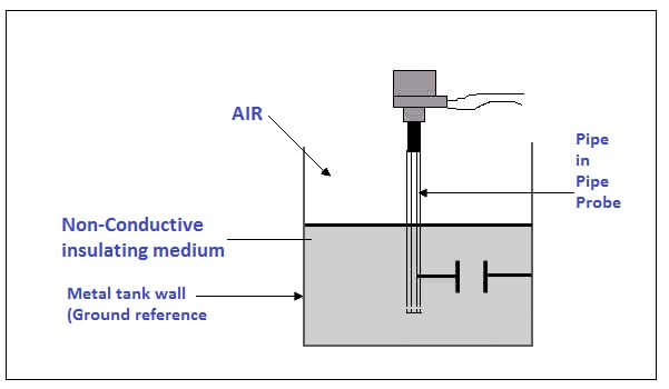
Capacitance level transmitters use the principle of the dielectric plate measurement technique to determine a level or interface measurement. A capacitor is formed when a level sensing electrode is installed in a vessel. The metal rod of the electrode acts as one plate of the capacitor and the tank wall (or reference electrode in a non-metallic vessel) acts as the other plate.
As level rises, the air or gas normally surrounding the electrode is displaced by material having a different dielectric constant. A change in the value of the capacitor takes place because the dielectric between the plates has changed. RF (radio frequency) capacitance instruments detect this change and convert it into a proportional output signal.
The capacitance relationship is illustrated with the following equation:
C = 0.225 K (A / D )
Where: C = Capacitance in picofarads
K = Dielectric constant of material
A = Area of plates in square inches
D = Distance between the plates in inches
In actual practice, capacitance change is produced in different ways depending on the material being measured and the level electrode selection. However, the basic principle always applies. If a higher dielectric material replaces a lower one, the total capacitance output of the system will increase. If the electrode is made larger (effectively increasing the surface area) the capacitance output increases; if the distance between measuring electrode and reference decreases, then the capacitance output decreases. Level is proportional to the capacitance measured. Since the capacitance is dependent on a stable dielectric of the medium throughout the height of the level column, the overall accuracy of either level or interface measurement will be impacted if the dielectric constant changes.
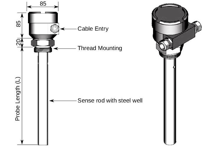
Installation instruction:
To install the level switch consider the following points for correct level measurement:
- Keep the sensor at least 50 mm (2″) away from any nozzle or tank wall.
- If multiple units are used, allow at least 100 mm (4″) between them, to prevent interference (mount diagonally if space is restricted).
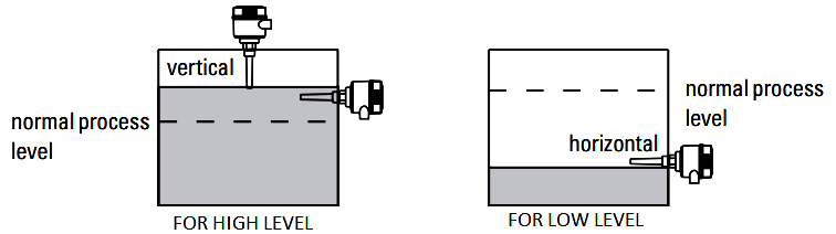
High level alarm
- Normally mounted into the vessel top
- Through the tank wall at the detection level
Low level alarm
- Mounted through the tank wall at the detection level
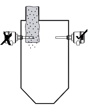
Process Connection:
- Keep unit out of path of falling material, or protect probe from falling material.
- Avoid areas where material build up occurs.
Wiring Connection:
Consider a Level Switch of siemens make for following procedures :
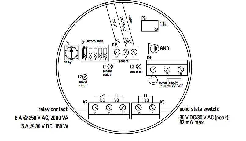
Calibration:
After properly mounted apply power to the unit. The green LED (L3) glows, indicating the unit is powered and use for operation. Use the potentiometers P1 and P2 to adjust the alarm delay and set point.
Follow the setup procedure for the application that most closely describes your operation:
Condition for various type process materials:
| Application | Material Setup | Conditions |
| General | • Dry solids
•Low viscosity liquids |
Sensor uncovered; min. 100 mm (4″) free space all around |
| Demanding | • Hygroscopic / wet solids
•High viscosity and high conductivity liquids |
Sensor immersed then uncovered; but retaining max. possible material buildup |
| Interface detection | • Liquid A / liquid B
•Foam / liquid |
immerse sensor in whichever material has lowest dielectric constant |
Calibration for general applications (Failsafe low, no delay) :
- Ensure the green power LED L3 is on.
- Set DIP switches S1 to S4 to OFF.
- Set DIP switch S5 ON (set-up mode).
- Ensure the probe is uncovered. If the yellow sensor status LED L1 is not on, turn the trip-point potentiometer P2 counter-clockwise until it just turns on.
- Turn the trip-point potentiometer P2 clockwise until LED L1 just turns off.
- Set DIP switch S5 to OFF (run mode).
Calibration for demanding applications (Failsafe low, no delay)
- Ensure that the green power LED L3 is on.
- Set DIP switches S1 to S4 to OFF.
- Set DIP switch S5 to ON (set-up mode).
- Turn the delay potentiometer P1 fully counterclockwise.
- Adjust the material level of the process so that the sensor is immersed.
- Adjust the material level of the process so that the sensor is uncovered, but retains as much buildup of material as possible on the sensor.
- If the yellow sensor status LED L1 is not on, turn the trip point potentiometer P2 counter-clockwise until it just turns on.
- Turn the trip point potentiometer P2 clockwise until LED L1 just turns off.
- Set DIP switch S5 to OFF (run mode).
Calibration for interface detection (Failsafe low, no delay) :
- Ensure that the green power LED L3 is on.
- Set DIP switches S1 to S4 to OFF. 3. Set DIP switch S5 to ON (set-up mode).
- Turn the delay potentiometer P1 fully counter-clockwise.
- Adjust the material level of the process so that the sensor is covered by the material with the lowest relative dielectric constant.
- If the yellow sensor status LED L1 is not on, turn the trip point potentiometer P2 counter-clockwise until it just turns on.
- Turn the trip point potentiometer P2 clockwise until LED L1 just turns off. 8. Set DIP switch S5 to OFF (run mode).
Note : Procedures vary from model to model.
Reference : Siemens Manuals


Sir articles are too informative..
I want to know whether it is possible to download the article from the app for future reference
Hi, ” Instrumentation Tools ” Android App has inbuilt save option for offline read.
I have a flowserve positiner named logix 3200. It’s hunting and not operating from dcs. Pls tell me the solution.