Inst ToolsInst ToolsInst Tools
  • Courses
  • Automation
    • PLC
    • Control System
    • Safety System
    • Communication
    • Fire & Gas System
  • Instrumentation
    • Design
    • Pressure
    • Temperature
    • Flow
    • Level
    • Vibration
    • Analyzer
    • Control Valve
    • Switch
    • Calibration
    • Erection & Commissioning
  • Interview
    • Instrumentation
    • Electrical
    • Electronics
    • Practical
  • Q&A
    • Instrumentation
    • Control System
    • Electrical
    • Electronics
    • Analog Electronics
    • Digital Electronics
    • Power Electronics
    • Microprocessor
  • Request
Search
  • Books
  • Software
  • Projects
  • Process
  • Tools
  • Basics
  • Formula
  • Power Plant
  • Root Cause Analysis
  • Electrical Basics
  • Animation
  • Standards
  • 4-20 mA Course
  • Siemens PLC Course
Reading: Phototransistor Circuit Example
Share
Notification Show More
Font ResizerAa
Inst ToolsInst Tools
Font ResizerAa
  • Courses
  • Design
  • PLC
  • Interview
  • Control System
Search
  • Courses
  • Automation
    • PLC
    • Control System
    • Safety System
    • Communication
    • Fire & Gas System
  • Instrumentation
    • Design
    • Pressure
    • Temperature
    • Flow
    • Level
    • Vibration
    • Analyzer
    • Control Valve
    • Switch
    • Calibration
    • Erection & Commissioning
  • Interview
    • Instrumentation
    • Electrical
    • Electronics
    • Practical
  • Q&A
    • Instrumentation
    • Control System
    • Electrical
    • Electronics
    • Analog Electronics
    • Digital Electronics
    • Power Electronics
    • Microprocessor
  • Request
Follow US
All rights reserved. Reproduction in whole or in part without written permission is prohibited.
Inst Tools > Blog > Electronic Devices & Circuits > Phototransistor Circuit Example

Phototransistor Circuit Example

Last updated: September 27, 2016 7:52 am
Editorial Staff
Electronic Devices & Circuits
No Comments
Share
1 Min Read
SHARE

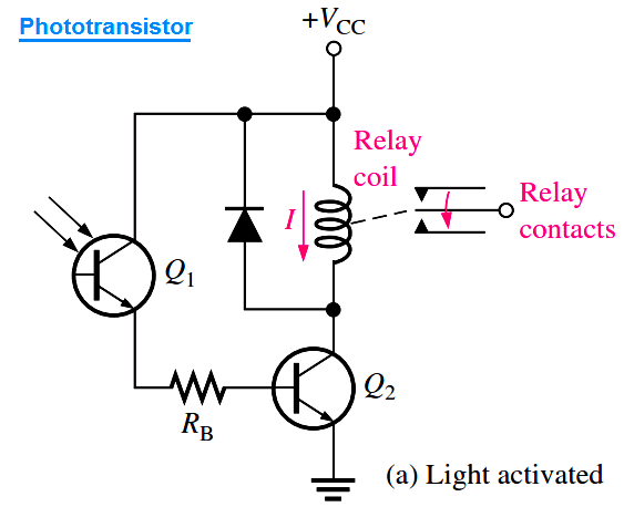
Phototransistors are used in a variety of applications. A light-operated relay circuit is shown in below Figure (a). The phototransistor Q1 drives the BJT Q2. When there is sufficient incident light on Q1, transistor Q2 is driven into saturation, and collector current through the relay coil energizes the relay. The diode across the relay coil prevents, by its limiting action, a large voltage transient from occurring at the collector of Q2 when the transistor turns off.
phototransistor-circuit

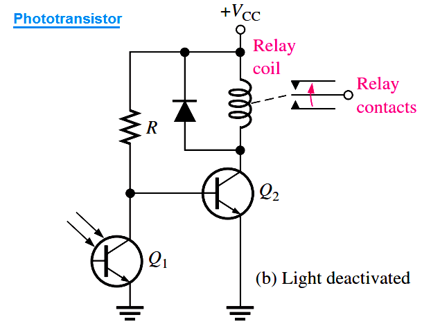
The below Figure (b) shows a circuit in which a relay is deactivated by incident light on the phototransistor. When there is insufficient light, transistor Q2 is biased on, keeping the relay energized. When there is sufficient light, phototransistor Q1 turns on; this pulls the base of Q2 low, thus turning Q2 off and de-energizing the relay.
phototransistor-circuit-example

Don't Miss Our Updates
Be the first to get exclusive content straight to your email.
We promise not to spam you. You can unsubscribe at any time.
Invalid email address
You've successfully subscribed !

Continue Reading

Electronic Symbols
Time Base Generator
Amplifiers Questions & Answers
Power MOSFET Safe Operating Area
Basics of Ohm’s Law
Optoisolator Working Principle
Share This Article
Facebook Whatsapp Whatsapp LinkedIn Copy Link
Share
Leave a Comment

Leave a Reply Cancel reply

Your email address will not be published. Required fields are marked *

Stay Connected

128.3kFollowersLike
69.1kFollowersFollow
210kSubscribersSubscribe
38kFollowersFollow

Categories

Explore More

Transistor as Amplifier
PIN Diode Working Principle
Forward Bias & Reverse Bias Diode Working Animation
CRT Fluorescent Screen
What is Kirchhoff’s Current Law
Resistors Principle & Applications
How to Test a Diode using Multimeter
Zener Diode Limiter

Keep Learning

energy-diagrams-for-insulator-semiconductor-and-conductor

Band Gap for Semiconductor Materials

reverse-biased varactor diode

Varactor Diode Operation

Permanent magnet moving coil instruments (PMMC)

Permanent Magnet Moving Coil Instruments (PMMC)

Comparison of MOSFET and BJT

Comparison of MOSFET and BJT

Ideal Diode Characteristics Curve

Difference between ideal diode & conventional diode

basic-electronics-questions-answers

Basic Electronics Questions & Answers

What is a Memristor

What is a Memristor? Principle, Advantages, Applications

Transistor Amplifier Working Principle

Learn More

Omron CX programmer shift register

The Concept of Shift Register in Omron PLC with Example

Resistance Temperature Detectors Troubleshooting Tips

Resistance Temperature Detectors Troubleshooting Tips

FF Function block Modes

FF Function block Modes

P & ID Valve Status Symbols

Piping and Instrumentation Drawing (P&ID) Tutorials – Part 4

Raspberry Pi Projects

200 Raspberry Pi Projects

DCS Troubleshooting Control Valve Loop

DCS Troubleshooting Control Valve Loop

HART Communication

HART Communication Protocol Overview

IACS Network

Remote Connectivity to Industrial Automation Systems

Menu

  • About
  • Privacy Policy
  • Copyright

Quick Links

  • Learn PLC
  • Helping Hand
  • Part Time Job

YouTube Subscribe

Follow US
All rights reserved. Reproduction in whole or in part without written permission is prohibited.
Welcome Back!

Sign in to your account

Username or Email Address
Password

Lost your password?