Inst ToolsInst ToolsInst Tools
  • Ask
  • Courses
  • Videos
  • Q & A
    • Interview
      • Instrumentation
      • Electronics
      • Electrical
      • Practical Questions
    • MCQ
      • Instrumentation MCQ
      • Electrical MCQ
      • Electronics MCQ
      • Control Systems MCQ
      • Analog Electronics MCQ
      • Digital Electronics MCQ
      • Power Electronics MCQ
      • Microprocessor MCQ
      • Multiple Choice Questions
  • EE
    • Electronics
      • Electronics Q & A
      • Electronic Basics
      • Electronic Devices & Circuits
      • Electronics Animation
      • Digital Electronics
    • Electrical
      • Electrical Basics
      • Electrical Q & A
      • Power Electronics
      • Electrical Machines
      • Electrical Animation
      • Power Systems
      • Switchgear & Protection
      • Transmission & Distribution
  • Measure
    • Control Valves
    • Calibration
    • Temperature
    • Pressure
    • Flow
    • Level
    • Analyzers
    • Switches
    • Vibration
    • Solenoid Valve
  • Control
    • PLC Tutorials
    • Control Systems
    • Safety Instrumented System (SIS)
    • Communication
    • Fire & Gas System
  • More
    • Design
    • Tools
    • Animation
    • Basics
    • Formulas
    • Standards
    • TextBooks
    • Common
    • Software
    • Excel Tools
    • Erection & Commissioning
    • Process Fundamentals
    • Videos
    • Books
Search
All rights reserved. Reproduction in whole or in part without written permission is prohibited.
Reading: Transistor as a Switch Working Principle
Share
Notification Show More
Font ResizerAa
Inst ToolsInst Tools
Font ResizerAa
  • Courses
  • PLC Tutorials
  • Control Systems
Search
  • Ask
  • Courses
  • Videos
  • Q & A
    • Interview
    • MCQ
  • EE
    • Electronics
    • Electrical
  • Measure
    • Control Valves
    • Calibration
    • Temperature
    • Pressure
    • Flow
    • Level
    • Analyzers
    • Switches
    • Vibration
    • Solenoid Valve
  • Control
    • PLC Tutorials
    • Control Systems
    • Safety Instrumented System (SIS)
    • Communication
    • Fire & Gas System
  • More
    • Design
    • Tools
    • Animation
    • Basics
    • Formulas
    • Standards
    • TextBooks
    • Common
    • Software
    • Excel Tools
    • Erection & Commissioning
    • Process Fundamentals
    • Videos
    • Books
Follow US
All rights reserved. Reproduction in whole or in part without written permission is prohibited.
Inst Tools > Blog > Electronic Devices & Circuits > Transistor as a Switch Working Principle

Transistor as a Switch Working Principle

Last updated: September 27, 2016 2:18 pm
Editorial Staff
Electronic Devices & Circuits Electronics Animation
No Comments
Share
2 Min Read
SHARE

Transistor Switch Animation

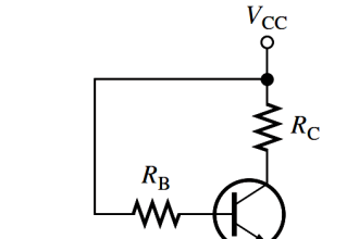
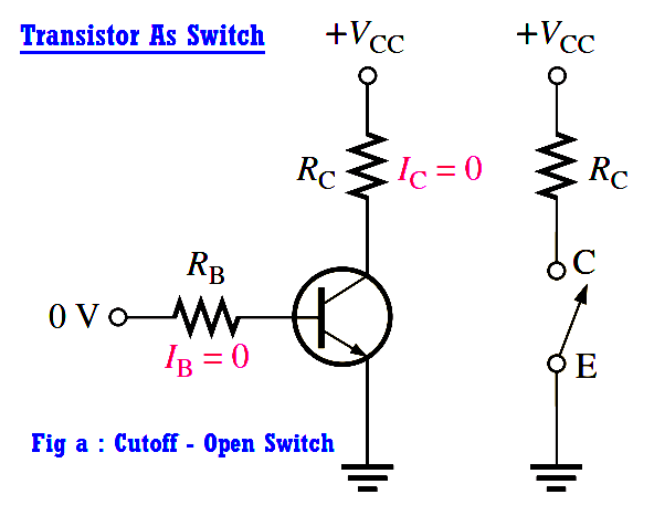
The below Figure illustrates the basic operation of a BJT as a switching device. In part (a), the transistor is in the cutoff region because the base-emitter junction is not forward-biased. In this condition, there is, ideally, an open between collector and emitter, as indicated by the switch equivalent.

Transistor as Switch in Cut off region

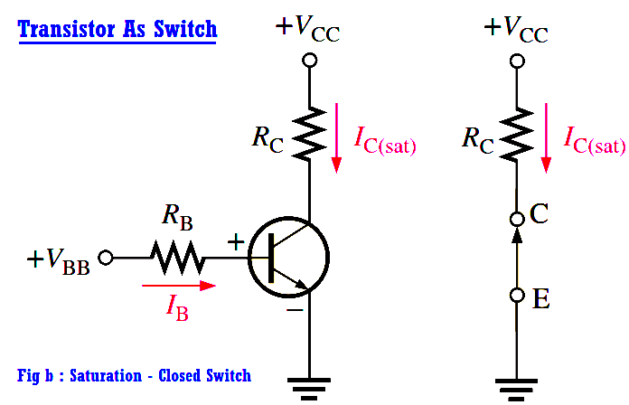
In part (b), the transistor is in the saturation region because the base-emitter junction and the base-collector junction are forward-biased and the base current is made large enough to cause the collector current to reach its saturation value. In this condition, there is, ideally, a short between collector and emitter, as indicated by the switch equivalent. Actually, a small voltage drop across the transister of up to a few tenths of a volt normally occurs, which is the saturation voltage, VCE(sat).

Transistor as Switch in Saturation region

Conditions in Cutoff : As mentioned before, a transistor is in the cutoff region when the base-emitter junction is not forward-biased. Neglecting leakage current, all of the currents are zero, and VCE is equal to VCC.

VCE(cutoff) = VCC

Conditions in Saturation : As you have learned, when the base-emitter junction is forward-biased and there is enough base current to produce a maximum collector current, the transistor is saturated. The formula for collector saturation current is

transistor-switch-formula

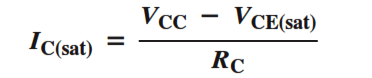
Since VCE(sat) is very small compared to VCC, it can usually be neglected.

The minimum value of base current needed to produce saturation is

transistor-in-saturated

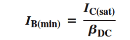
Normally, IB should be significantly greater than IB(min) to ensure that the transistor is saturated.

Don't Miss Our Updates
Be the first to get exclusive content straight to your email.
We promise not to spam you. You can unsubscribe at any time.
Invalid email address
You've successfully subscribed !
Diode Limiters/Clippers Operation
Full Wave Bridge Rectifier Operation
Bipolar Junction Transistor Construction
Comparison of Half wave Rectifiers and Full wave Rectifiers
Applications of Photo diodes
Share This Article
Facebook Whatsapp Whatsapp LinkedIn Copy Link
Share
Leave a Comment

Leave a Reply Cancel reply

Your email address will not be published. Required fields are marked *

Stay Connected

128.3kFollowersLike
69.1kFollowersFollow
208kSubscribersSubscribe
38kFollowersFollow

Categories

Recent Comments

  • Kamli on Top Free PLC Software
  • Guifty Shimica on Top Non-PLC Certification Courses for Automation Professionals
  • Guifty Shimica on Top Non-PLC Certification Courses for Automation Professionals
  • MIHARITSOA Aina Sitraka on Top Non-PLC Certification Courses for Automation Professionals

Related Articles

Transistor Emitter Feedback Bias

Transistor Emitter Feedback Bias

diode-basic-structure-symbol

Forward Bias & Reverse Bias of a Diode

How a Multi Color LED Works

How a Multi Color LED Works ?

Dependent Current Source

Dependent Current Source

Electronic Symbols List

Electronic Symbols

temperature compensation circuit for PMMC

PMMC Temperature Compensation

parallel-resistors-circuit-example

Series and Parallel Resistors

What is a Filter Circuit

What is a Filter Circuit ?

More Articles

Electronic Devices & Circuits Objective Questions

Electronic Devices & Circuits Quiz – Set 5

Control Systems Stability and Algebraic Criteria

Routh-Hurwitz Stability Criterion

Actuator Sensor Interface (ASi) Protocol in PLC

Actuator Sensor Interface (ASi) Protocol in PLC

PLC Program Paint Spraying

PLC Program for Paint Spraying

What is a Process Alarm

What is a Process Alarm? Types of Alarms

Transformers Questions & Answers Part-2

Transformers Questions & Answers Part-2

Allen Bradley PLC ControlLogix Hardware

Allen Bradley PLC ControlLogix Hardware

Configuration of Siemens VFD Using TIA Portal

Configuration of Siemens VFD Using TIA Portal Start drive

Follow US
All rights reserved. Reproduction in whole or in part without written permission is prohibited.
Welcome Back!

Sign in to your account

Username or Email Address
Password

Lost your password?