Inst ToolsInst ToolsInst Tools
  • Courses
  • Automation
    • PLC
    • Control System
    • Safety System
    • Communication
    • Fire & Gas System
  • Instrumentation
    • Design
    • Pressure
    • Temperature
    • Flow
    • Level
    • Vibration
    • Analyzer
    • Control Valve
    • Switch
    • Calibration
    • Erection & Commissioning
  • Interview
    • Instrumentation
    • Electrical
    • Electronics
    • Practical
  • Q&A
    • Instrumentation
    • Control System
    • Electrical
    • Electronics
    • Analog Electronics
    • Digital Electronics
    • Power Electronics
    • Microprocessor
  • Request
Search
  • Books
  • Software
  • Projects
  • Process
  • Tools
  • Basics
  • Formula
  • Power Plant
  • Root Cause Analysis
  • Electrical Basics
  • Animation
  • Standards
  • 4-20 mA Course
  • Siemens PLC Course
Reading: Transistor Cut off, Saturation & Active Regions
Share
Notification Show More
Font ResizerAa
Inst ToolsInst Tools
Font ResizerAa
  • Courses
  • Design
  • PLC
  • Interview
  • Control System
Search
  • Courses
  • Automation
    • PLC
    • Control System
    • Safety System
    • Communication
    • Fire & Gas System
  • Instrumentation
    • Design
    • Pressure
    • Temperature
    • Flow
    • Level
    • Vibration
    • Analyzer
    • Control Valve
    • Switch
    • Calibration
    • Erection & Commissioning
  • Interview
    • Instrumentation
    • Electrical
    • Electronics
    • Practical
  • Q&A
    • Instrumentation
    • Control System
    • Electrical
    • Electronics
    • Analog Electronics
    • Digital Electronics
    • Power Electronics
    • Microprocessor
  • Request
Follow US
All rights reserved. Reproduction in whole or in part without written permission is prohibited.
Inst Tools > Blog > Electronic Devices & Circuits > Transistor Cut off, Saturation & Active Regions

Transistor Cut off, Saturation & Active Regions

Last updated: September 27, 2016 2:38 pm
Editorial Staff
Electronic Devices & Circuits
2 Comments
Share
4 Min Read
SHARE

The below Fig. (i) shows CE transistor circuit while Fig.(ii) shows the output characteristcs along with the d.c. load line.

(i) Cut off. The point where the load line intersects the IB = 0 curve is known ascut off. At this point, IB = 0 and only small collector current (i.e. collector leakage current ICEO) exists. At cut off, the base-emitter junction no longer remains forward biased and normal transistor action is lost. The collector-emitter voltage is nearly equal to VCC i.e. VCE (cut off) = VCC

Transistor-cut-off-saturation-active-regions

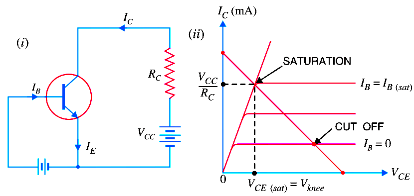
(ii) Saturation. The point where the load line intersects the IB = IB(sat) curve is called saturation. At this point, the base current is maximum and so is the collector current. At saturation, collector-base junction no longer remains reverse biased and normal transistor action is lost.

Transistor-saturation-region-formula

If base current is greater than IB(sat), then collector current cannot increase because collector-base junction is no longer reverse-biased.

(iii) Active region. The region between cut off and saturation is known as active region. In the active region, collector-base junction remains reverse biased while base-emitter junction remains forward biased. Consequently, the transistor will function normally in this region.

Note. We provide biasing to the transistor to ensure that it operates in the active region. The reader may find the detailed discussion on transistor biasing in the next chapter.

transistor diode symbol

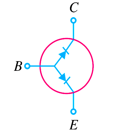
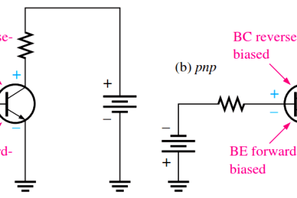
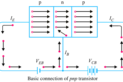
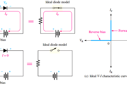
Summary. A transistor has two pn junctions i.e., it is like two diodes. The junction between base and emitter may be called emitter diode. The junction between base and collector may be called collector diode. We have seen above that transistor can act in one of the three states : cut-off, saturated and active.The state of a transistor is entirely determined by the states of the emitter diode and collector diode [See Above Fig]. The relations between the diode states and the transistor states are :

CUT-OFF : Emitter diode and collector diode are OFF.

ACTIVE : Emitter diode is ON and collector diode is OFF.

SATURATED : Emitter diode and collector diode are ON.

In the active state, collector current [See Below Fig (i)] is β times the base current (i.e. IC = IB). If the transistor is cut-off, there is no base current, so there is no collector or emitter current. That is collector emitter pathway is open [See Below Fig.]

(ii)]. In saturation, the collector and emitter are, in effect, shorted together. That is the transistor behaves as though a switch has been closed between the collector and emitter [See Below Fig. (iii)].

Transistor-regions

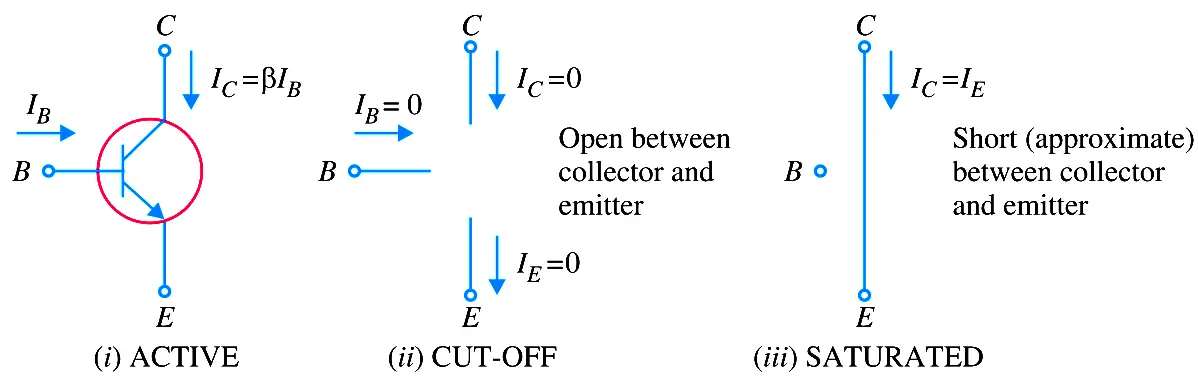
Note. When the transistor is in the active state, IC = IB. Therefore, a transistor acts as an amplifier when operating in the active state. Amplification means linear amplification. In fact, small signal amplifiers are the most common linear devices.

Don't Miss Our Updates
Be the first to get exclusive content straight to your email.
We promise not to spam you. You can unsubscribe at any time.
Invalid email address
You've successfully subscribed !

Continue Reading

Dependent Current Source
Ideal Diode Characteristics
Power MOSFET
Methods of Transistor Biasing
Transistor Amplifier Working Principle
Transistor as a Switch Working Principle
Share This Article
Facebook Whatsapp Whatsapp LinkedIn Copy Link
Share
2 Comments
  • Chethan S says:
    December 17, 2021 at 5:41 am

    A small correction, in the note point at last. In the active region Ic=Beta times Ib. Please rectify this.

    Reply
    • Sam Quentin says:
      September 3, 2023 at 10:47 am

      Was curious about that.
      Thanks for the clarification.

      Reply

Leave a Reply Cancel reply

Your email address will not be published. Required fields are marked *

Stay Connected

128.3kFollowersLike
69.1kFollowersFollow
210kSubscribersSubscribe
38kFollowersFollow

Categories

Explore More

Center Tapped Full Wave Rectifier Operation
Why Silicon is preferred over Germanium ?
Full Wave Voltage Doubler using Diodes
What is a Memristor? Principle, Advantages, Applications
Freewheeling Diode Working Principle
Basic Transistor Amplifier Circuit Principle
Applications of Photo diodes
Amplifiers Questions & Answers

Keep Learning

Semiconductors Diodes Questions & Answers

Semiconductors Diodes Questions & Answers

Cathode Ray Tube Deflection System

Cathode Ray Tube Deflection System

Photodiode as Variable Resistance Device

Photodiode as Variable Resistance Device

example-of-KCL

What is Kirchhoff’s Current Law

Capacitively Coupled Multistage Transistor Amplifier

Capacitively Coupled Multistage Transistor Amplifier

parallel-resistors-circuit-example

Series and Parallel Resistors

Capacitor Filter Operation

Capacitor Filter Operation

Electronic Symbols List

Electronic Symbols

Learn More

wedge Flow meter

What is a Segmental Wedge Flow Meter?

Temperature Scanner

Applications of Temperature Scanner

Metal Seated Ball Valves

Metal Seated Valves and Soft Seated Valves : Differences

PLC Program for Analog Input Sampling

PLC Analog Input Sampling Ladder Logic

Stability in Frequency Domain

Time Domain Analysis

Difference Between Modbus and Profibus

Difference Between Modbus and Profibus

Valve Face to Face Dimension

Face to Face Dimension of Control Valve

relay-safety-in-plc

How to Reduce Relay Noise in PLC Systems?

Menu

  • About
  • Privacy Policy
  • Copyright

Quick Links

  • Learn PLC
  • Helping Hand
  • Part Time Job

YouTube Subscribe

Follow US
All rights reserved. Reproduction in whole or in part without written permission is prohibited.
Welcome Back!

Sign in to your account

Username or Email Address
Password

Lost your password?