An interesting variation on this theme of direct hydrostatic pressure measurement is the use of a purge gas to measure hydrostatic pressure in a liquid-containing vessel.
This eliminates the need for direct contact of the process liquid against the pressure-sensing element, which can be advantageous if the process liquid is corrosive.
Such systems are often called bubble tube or dip tube systems, the former name being appropriately descriptive for the way purge gas bubbles out the end of the tube as it is submerged in process liquid.
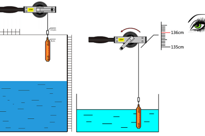
A very simple bubbler system may be simulated by gently blowing air through a straw into a glass of water, maintaining a steady rate of bubbles exiting the straw while changing the depth of the straw’s end in the water:
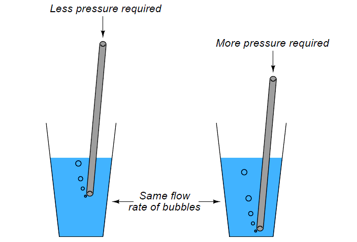
The deeper you submerge the straw, the harder it becomes to blow bubbles out the end with your breath. The hydrostatic pressure of the water at the straw’s tip becomes translated into air pressure in your mouth as you blow, since the air pressure must just exceed the water’s pressure in order to escape out the end of the straw.
So long as the flow rate of air is modest (no more than a few bubbles per second), the air pressure will be very nearly equal to the water pressure, allowing measurement of water pressure (and therefore water depth) at any point along the length of the air tube.
If we lengthen the straw and measure pressure at all points throughout its length, it will be the same as the pressure at the submerged tip of the straw (assuming negligible friction between the moving air molecules and the straw’s interior walls):
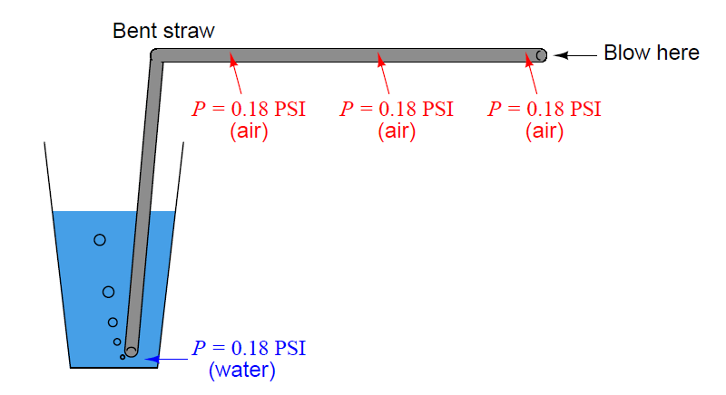
This is how industrial “bubbler” level measurement systems work: a purge gas is slowly introduced into a “dip tube” submerged in the process liquid, so that no more than a few bubbles per second of gas emerge from the tube’s end.
Gas pressure inside all points of the tubing system will (very nearly) equal the hydrostatic pressure of the liquid at the tube’s submerged end.
Any pressure-measuring device tapped anywhere along the length of this tubing system will sense this pressure and be able to infer the depth of the liquid in the process vessel without having to directly contact the process liquid.
Bubbler-style liquid level measurement systems are especially useful when the process liquid in question is highly corrosive, prone to plugging sample ports, or in any other way objectionable to have in direct contact with a pressure sensor.
Unlike pressure sensors which must use diaphragms or other flexible (usually metallic) sensing elements and therefore may only be constructed from a limited range of materials, a dip tube need not be flexible and therefore may be constructed of any material capable of withstanding the process liquid.
A process liquid so corrosive that non-metallic vessels are required to hold it would preclude direct contact with a metal pressure gauge or pressure transmitter, but would be easily measured with a bubbler system provided the dip tube were made out of plastic, ceramic, or some other material immune to corrosion.
A process liquid so laden with solids that it plugs up any non-flowing port would preclude pressure measurement via a sample port and impulse line, but would be easily measured by a bubbler system where the dip tube is continuously purged with clean gas.
Level measurement applications where direct contact with the pressure sensor would render access to that sensor inconvenient or even impossible are made much more practical by using a bubbler system, where the pressure sensor may be located anywhere along the dip tube’s length and therefore easily located where maintenance personnel can access it.
Excessive purge gas flow through the tube will result in additional pressure caused by frictional pressure drop along the tube’s length, causing the pressure-sensing instrument to falsely register high.
A key detail of any practical bubble tube system, therefore, is some means to monitor and control gas flow through the tube.
A common construction uses either a rotameter or a sight feed bubbler to monitor purge gas flow rate, with a needle valve to restrict that flow:

A more sophisticated solution to the problem of purge gas flow rate is to install a flow-regulator in lieu of a pressure regulator and needle valve, a mechanism designed to automatically monitor and throttle gas flow to maintain a constant purge rate.
Flow regulators compensate for changes in dip tube pressure and in gas supply pressure, eliminating the need for a human operator to periodically adjust a needle valve.
Limiting the flow of purge gas is also important if that purge gas is expensive to obtain. For bottled gases such as nitrogen (necessary in processes requiring a non-reactive purge), the cost of purchasing tanks of compressed gas is obvious.
For air-purged systems the cost is still present, but not so obvious: the cost of running an air compressor to maintain continuous purge air pressure.
Either way, limiting the flow rate of purge gas in a bubbler system yields economic benefits aside from increased measurement accuracy.
As with all purged systems, certain criteria must be met for successful operation. Listed here are some of them:
- The purge gas supply must be reliable: if the flow stops for any reason, the level measurement will cease to be accurate, and the dip tube may even plug with debris!
- The purge gas supply pressure must exceed the hydrostatic pressure at all times, or else the level measurement range will fall below the actual liquid level.
- The purge gas flow must be maintained at a low rate, to avoid pressure drop errors (i.e. excess pressure measured due to friction of the purge gas through the tube).
- The purge gas must not adversely react with the process.
- The purge gas must not contaminate the process.
- The purge gas must be reasonable in cost, since it will be continuously consumed over time.
One measurement artifact of a bubble tube system is a slight variation in pressure each time a new bubble breaks away from the end of the tube.
The amount of pressure variation is approximately equal to the hydrostatic pressure of process fluid at a height equal to the diameter of the bubble, which in turn will be approximately equal to the diameter of the bubble tube.
For example, a 1/4 inch diameter dip tube will experience pressure oscillations with a peak-to-peak amplitude of approximately 1 4 inch elevation of process liquid.
The frequency of this pressure oscillation, of course, will be equal to the rate at which individual bubbles escape out the end of the dip tube.
Usually, this is a small variation when considered in the context of the measured liquid height in the vessel.
A pressure oscillation of approximately 1/4 inch compared to a measurement range of 0 to 10 feet, for example, is only about 0.2% of span.
Modern pressure transmitters have the ability to “filter” or “damp” pressure variations over time, which is a useful feature for minimizing the effect such a pressure variation will have on system performance.
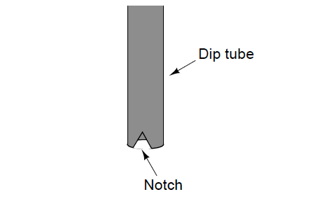
A way to help minimize this effect is to place small V-shaped notches at the end of the dip tube, to help bubbles escape at sizes smaller than the tube’s diameter:
Credits : Tony R. Kuphaldt – Creative Commons Attribution 4.0 License


Great explanation, very clear. However, a question – since there’s a quite predictable signal deviation from the bubble release events, why not use that as a diagnostic for monitoring gas flow as well, so the system can alarm if level is low/high, but also can alarm if gas flow is decreasing or increasing beyond set limits?
Nice explanation of the basics