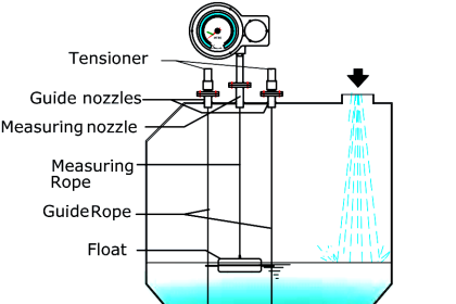
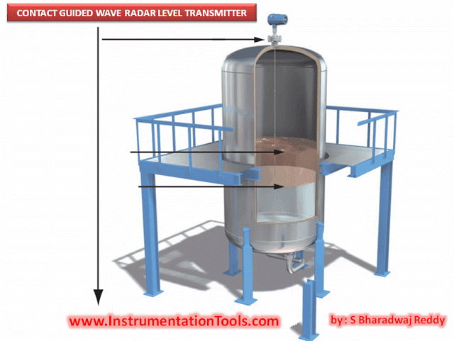
Servo Level Transmitter Principle
A very thin measuring wire B is wound onto measuring drum C having a certain length of precisely machined spiral groove.
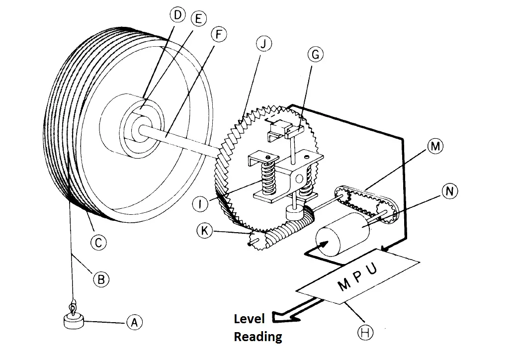
Measuring drum C is connected to Driving shaft F through magnet coupling D, E and rotates forward and backward according to movement of gear-down unit J, K and stepping motor N. A worm gear J, which is located on the same axis as Driving shaft F, is connected to Driving shaft F through Spring I.
By this arrangement, tension onto Measuring wire B can be precisely detected by measuring distortion of Spring I by Balancer G. A Displacer A, of which density is higher than that of liquid to be measured, is connected to one end of Measuring wire B. The weight of Displacer A always gives downforce tension to Driving shaft F. In normal measurement condition, Stepping motor N is controlled by signal from Balancer G to give Measuring wire B a slightly less and constant tension than the weight of Displacer A. In this way, Displacer A always follows liquid surface with stable draft line.
Thus, rotating angle of Measuring drum C which corresponds to length of unwound Measuring wire B represents height of liquid in tank.
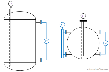
By adjusting the control level of tension T onto measuring wire B, interface of two liquids having different density can also be measured. Also, by sinking displacer into liquid and measuring the tension T onto measuring wire B, the liquid density can be detected and measured.
The signal from Balancer G is either fully digitalized or a 4-20mA signal output. Stepper motor N, having high resolution, is controlled by Microprocessor unit H. This digitized servo operation system offers high liquid following capability and stability in operation compared to existing analog control method.
The angle of Measuring drum rotation is obtained from the number of steps of Stepper Motor N. This remarkably improves the resolution of liquid level measurement of 0.1 mm.
Source : tokyokeiso.co.jp