Inst ToolsInst ToolsInst Tools
  • Ask
  • Courses
  • Videos
  • Q & A
    • Interview
      • Instrumentation
      • Electronics
      • Electrical
      • Practical Questions
    • MCQ
      • Instrumentation MCQ
      • Electrical MCQ
      • Electronics MCQ
      • Control Systems MCQ
      • Analog Electronics MCQ
      • Digital Electronics MCQ
      • Power Electronics MCQ
      • Microprocessor MCQ
      • Multiple Choice Questions
  • EE
    • Electronics
      • Electronics Q & A
      • Electronic Basics
      • Electronic Devices & Circuits
      • Electronics Animation
      • Digital Electronics
    • Electrical
      • Electrical Basics
      • Electrical Q & A
      • Power Electronics
      • Electrical Machines
      • Electrical Animation
      • Power Systems
      • Switchgear & Protection
      • Transmission & Distribution
  • Measure
    • Control Valves
    • Calibration
    • Temperature
    • Pressure
    • Flow
    • Level
    • Analyzers
    • Switches
    • Vibration
    • Solenoid Valve
  • Control
    • PLC Tutorials
    • Control Systems
    • Safety Instrumented System (SIS)
    • Communication
    • Fire & Gas System
  • More
    • Design
    • Tools
    • Animation
    • Basics
    • Formulas
    • Standards
    • TextBooks
    • Common
    • Software
    • Excel Tools
    • Erection & Commissioning
    • Process Fundamentals
    • Videos
    • Books
Search
All rights reserved. Reproduction in whole or in part without written permission is prohibited.
Reading: Ultrasonic Level Switch Working Principle
Share
Notification Show More
Font ResizerAa
Inst ToolsInst Tools
Font ResizerAa
  • Courses
  • PLC Tutorials
  • Control Systems
Search
  • Ask
  • Courses
  • Videos
  • Q & A
    • Interview
    • MCQ
  • EE
    • Electronics
    • Electrical
  • Measure
    • Control Valves
    • Calibration
    • Temperature
    • Pressure
    • Flow
    • Level
    • Analyzers
    • Switches
    • Vibration
    • Solenoid Valve
  • Control
    • PLC Tutorials
    • Control Systems
    • Safety Instrumented System (SIS)
    • Communication
    • Fire & Gas System
  • More
    • Design
    • Tools
    • Animation
    • Basics
    • Formulas
    • Standards
    • TextBooks
    • Common
    • Software
    • Excel Tools
    • Erection & Commissioning
    • Process Fundamentals
    • Videos
    • Books
Follow US
All rights reserved. Reproduction in whole or in part without written permission is prohibited.
Inst Tools > Blog > Animation > Ultrasonic Level Switch Working Principle

Ultrasonic Level Switch Working Principle

Last updated: March 13, 2017 6:58 am
Editorial Staff
Animation How It Works Level Measurement Switches
3 Comments
Share
5 Min Read
SHARE

Ultrasonic Gap Switch Theory

An ultrasonic switch is a device that uses inaudible high-frequency sound (ultrasound) to detect the presence or absence of a liquid at a designated point. The device consists of an electronic control unit and a sensor. Ultrasonic level switches use the properties of sound transmission in vapor and liquids to detect liquid level. When sound travels in air, it loses a great deal of signal strength. When traveling in liquid, sound retains almost all of its signal strength.Ultrasonic Level Switch Working Animation

To detect liquid level, we must determine if there is a liquid or gas (air) in the gap. Since liquids have a higher density than gasses, it is easier to transmit sound through them. One side of the sensor gap transmits sound, the other side detects it. When liquid is present, a high amount of sound is received at the detection side. When gas (air) is present, a small amount of sound is received. The electronics detect this difference and switch a relay accordingly.

Ultrasonic switch sensors contain two piezoelectric crystals, one transmits sound and one receives sound. Each crystal is mounted on one side of a gap in the metal sensor. The transmit crystal generates high frequency sound (1MHz to 3 MHz) that is directed across the gap to the receiver crystal. The receiver crystal converts the sound energy received into an electric signal, which is processed by the electronics to determine if the gap has liquid or air in it.

Ultrasonic Gap Switch/Level Switch Working Principle

Ultrasonic Switches employ a pair of piezoelectric crystals that are encapsulated within epoxy at the tip of the transducer. The crystals are comprisedUltrasonic Gap Switch Working Principle 
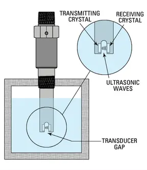
of a ceramic material that vibrates at a given frequency when subjected to an applied voltage. When the voltage is sent from the electronics, one of the two crystals, the “transmitting crystal” converts the voltage to an ultrasonic signal.

The presence of liquid within the transducer gap allows the second crystal, the “receiving crystal” to sense the ultrasonic signal and converts it back into an electronic signal. The signal informs the electronics that liquid is present within the transducer gap. If no liquid is present, the ultrasonic signal is attenuated and cannot be detected by the receiving crystal.

The ultrasonic transducer continuously monitors the gap to determine the presence of liquid. When used as a high-level switch, the electronics will immediately actuate a relay if it detects a wet gap.Similarly when used as a low-level switch, it continuously monitors the gap for a dry condition.

Applications:

Ultrasonic level switches can be used in a wide variety of applications without any calibration or setup. However, there are limitations to the types of process they will work in.

The factors below must be taken into consideration before selecting an ultrasonic level switch for your application.

 Liquids only – the process media must be a liquid. The ultrasonic level switch cannot detect the difference between two gases or a gas and a solid. The even density of a liquid is required for proper detection.

 Clean liquids only – a liquid that has too high a percentage of solids will not transmit sound well enough to allow detection. Typically 5% suspended solids are the maximum amount allowed.

 The liquid must flow – an application where the liquid cannot drain out of the sensor gap will cause false alarms. If a liquid is too viscous to flow out of a 3/4” gap then the unit will not operate properly. Sometimes this can be solved by different mounting, but some liquids are just too viscous.

 No (or few) bubbles – especially in fluids with a higher viscosity. Large bubbles in thick fluids will block the sound signal from crossing the gap. Low viscosity fluids can have a fairly large amounts of bubbles as they tend to be very small (Alka-Seltzer in water). If these guidelines are properly observed, the ultrasonic level switches will provide trouble-free operation without any calibration or periodic adjustment.

Also Read: Anti surge Controller Working Principle

Don't Miss Our Updates
Be the first to get exclusive content straight to your email.
We promise not to spam you. You can unsubscribe at any time.
Invalid email address
You've successfully subscribed !
Coriolis Mass Flow Meter Working Principle
Solenoid Valves Types, Principle & Animation
Temperature Switch Working Principle
NDIR Gas Analyser Working Principle
DP Diaphragm Capillary Seal Level instrument Calibration Procedure
Share This Article
Facebook Whatsapp Whatsapp LinkedIn Copy Link
Share
3 Comments
  • randy m. catalan says:
    December 18, 2015 at 11:31 pm

    thanks for additional information it helps a lot

    Reply
    • sagar bhagat says:
      February 20, 2016 at 7:37 am

      Awesome ? dear and thank you for your information

      Reply
  • Arpit Doshi says:
    February 22, 2016 at 8:09 am

    NIce one..!!

    Reply

Leave a Reply Cancel reply

Your email address will not be published. Required fields are marked *

Stay Connected

128.3kFollowersLike
69.1kFollowersFollow
208kSubscribersSubscribe
38kFollowersFollow

Categories

Recent Comments

  • Guifty Shimica on Top Non-PLC Certification Courses for Automation Professionals
  • Guifty Shimica on Top Non-PLC Certification Courses for Automation Professionals
  • MIHARITSOA Aina Sitraka on Top Non-PLC Certification Courses for Automation Professionals
  • Vaishnavi on Free Instrumentation Course for Trainee Engineers

Related Articles

Quartzoid Bulb Detector Working Principle

Fire Water Sprinklers Working Principle

Level Transmitter

What is a Bridle?

Magnatic Level Indicators Working Animation

Magnetic Level Indicators Working Animation

Hydrostatic Tank Gauging (HTG)

Hydrostatic Tank Gauging (HTG)

Turbine Flow Meters Working Animation

Turbine Flow Meters Animation

Sinking and Sourcing Devices Operation

PLC Sinking and Sourcing Explanation

Limit Switch Installation

What is a Limit Switch ?

Capacitance Level measurement principle

Capacitance Level Sensor Principle, Limitations, Installation & Calibration

More Articles

The Control Valve Stroke Test Procedure

Control Valve Stroke Test Procedure

DCS

DCS

Gas Turbine Interview Questions and Answers

Gas Turbine Interview Questions and Answers

Digital Electronics Multiple Choice Questions

Half Subtractor and Full Subtractor Objective Questions

Advantages and Disadvantages of Network Topology

Advantages and Disadvantages of Network Topologies

Fire and Gas (F&G) Mapping: Methodology, Performance Targets, Acceptance Criteria

How to use Fire Fighting Hydrant

Fire and Safety

energized-to-safe-loop

Energize to Safe Loop philosophy

Follow US
All rights reserved. Reproduction in whole or in part without written permission is prohibited.
Welcome Back!

Sign in to your account

Username or Email Address
Password

Lost your password?