Inst ToolsInst ToolsInst Tools
  • Courses
  • Automation
    • PLC
    • Control System
    • Safety System
    • Communication
    • Fire & Gas System
  • Instrumentation
    • Design
    • Pressure
    • Temperature
    • Flow
    • Level
    • Vibration
    • Analyzer
    • Control Valve
    • Switch
    • Calibration
    • Erection & Commissioning
  • Interview
    • Instrumentation
    • Electrical
    • Electronics
    • Practical
  • Q&A
    • Instrumentation
    • Control System
    • Electrical
    • Electronics
    • Analog Electronics
    • Digital Electronics
    • Power Electronics
    • Microprocessor
Search
  • Books
  • Software
  • Projects
  • Process
  • Tools
  • Basics
  • Formula
  • Power Plant
  • Root Cause Analysis
  • Electrical Basics
  • Animation
  • Standards
  • 4-20 mA Course
  • Siemens PLC Course
Reading: Microwave Barrier Level Switch Working Principle
Share
Notification Show More
Font ResizerAa
Inst ToolsInst Tools
Font ResizerAa
  • Courses
  • Design
  • PLC
  • Interview
  • Control System
Search
  • Courses
  • Automation
    • PLC
    • Control System
    • Safety System
    • Communication
    • Fire & Gas System
  • Instrumentation
    • Design
    • Pressure
    • Temperature
    • Flow
    • Level
    • Vibration
    • Analyzer
    • Control Valve
    • Switch
    • Calibration
    • Erection & Commissioning
  • Interview
    • Instrumentation
    • Electrical
    • Electronics
    • Practical
  • Q&A
    • Instrumentation
    • Control System
    • Electrical
    • Electronics
    • Analog Electronics
    • Digital Electronics
    • Power Electronics
    • Microprocessor
Follow US
All rights reserved. Reproduction in whole or in part without written permission is prohibited.
Inst Tools > Blog > Animation > Microwave Barrier Level Switch Working Principle

Microwave Barrier Level Switch Working Principle

Last updated: June 18, 2019 6:53 pm
Editorial Staff
Animation Level Measurement Switches
1 Comment
Share
2 Min Read
SHARE

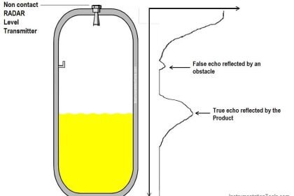
Non-contact point level detection in bulk solids

In many cases where contact methods are limited, microwave barriers are the appropriate solution.

They avoid jamming, indicate point levels, solve positioning and counting tasks, provide non-contact measurement and are thus, free of wear and tear.

Typical products to be measured are wood chips, paper and carton chips, lime, pebbles, sand or even bags and complete boxes.

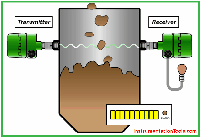
Microwave Barrier Switch detects the upper and lower limits of silo, hopper, etc… The microwave system enables non-contact detection and easy maintenance.

Further the mounting positions can be easily decided because detection works when the accumulation of material blocks the straight line between transmitter and receiver.

Principle

Microwaves can pass through walls made of insulators with low permittivity, such as plastics, glasses, died bricks, woods and ceramics.

The microwave barrier switch can detect the presence or non-presence of materials inside containers made of low permittivity materials without making any contact with the actual materials inside.

The absorption of microwaves is used for the supervision of limit values in microwave barriers. The microwave emitter and receiver form a radiation barrier. A narrow beam runs through the tank on the level which is to be monitored.

As soon as the medium enters the radiation area, the microwave signal is damped so that only a small part reaches the receiver. This is recognized and used for triggering the switching signal.

This is true, on principle:

High density = high damping

Low density = low damping

microwave-barrier-level-switch-principle

Advantages

  • Adjustable sensitivity
  • Flush mounted, non-contact measurement
  • No wear and tear or maintenance with long service life
  • Easy installation and commissioning
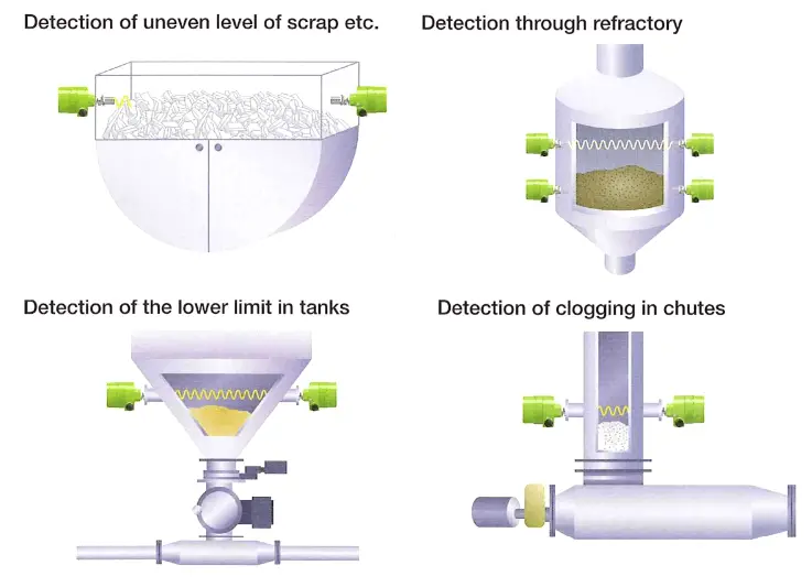
Applications:

micro-barrier-switch-applications

Article Source : matsushima-m-tech

Don't Miss Our Updates
Be the first to get exclusive content straight to your email.
We promise not to spam you. You can unsubscribe at any time.
Invalid email address
You've successfully subscribed !

Continue Reading

Four Way Solenoid Valve Working Principle
What is Seal-in Circuit ?
Effects of Symmetric and Asymmetric Capillary Tube Pressure Measurement
Types of Tank Gauging Level Measurement Systems
Basics of Level Measurement
Types of Limit Switches – Principle, Advantages, Disadvantages
Share This Article
Facebook Whatsapp Whatsapp LinkedIn Copy Link
Share
1 Comment
  • Md Makhuj Rabbi says:
    December 3, 2016 at 4:01 pm

    Thanks

    Reply

Leave a Reply Cancel reply

Your email address will not be published. Required fields are marked *

Stay Connected

128.3kFollowersLike
69.1kFollowersFollow
210kSubscribersSubscribe
38kFollowersFollow

Categories

Explore More

Radiation based Level Sensor Principle
Displacer Interface Level Measurement
Level Gauge Design
How a 4-20mA Transmitter Works?
Principle of Flow Switch
Potentiometer Working Principle Animation
Interface Level Measurement using DP Transmitter
Working Principle of Pressure Gauge

Keep Learning

Drum Level Compensation of DP Transmitter

Drum Level Compensation and Range Calculation of DP Transmitter

Limit Switch Installation

What is a Limit Switch ?

Transparent Level Gauge

Level Indicators Working Principle

Displacement Level Transmitter in situ calibration

Displacer (buoyancy) Level Transmitter Principle, Limitations, Design, Installation & Calibration

Radar and Ultrasonic Level Transmitter Problems Troubleshooting

Radar and Ultrasonic Level Transmitter Practical Problems Troubleshooting

DP Diaphragm Capillary Seal Level instrument

DP Diaphragm Capillary Seal Level instrument Calibration Procedure

AND Gate Logic Animation

Digital Building Blocks – GATES

Non-Contacting-Radar-Level-Transmitter-Animation

Non Contacting Radar Level Transmitter Animation

Learn More

PLC Program Upload

How to Upload Siemens PLC Programs?

Common Valve Abbreviations

Common Valve Abbreviations in US Engineering Drawings

Dall Tube Flow Meter Working Principle

Dall Tube Flow Meter – Principle, Advantages, Disadvantages

Difference between Soft Starter and VFD

Difference between Soft Starter and VFD

Solenoid Actuated Valves

Solenoid Actuated Valves

Single Push button to ON and OFF a Bulb using Ladder Logic

Single Push button to ON and OFF a Bulb using Ladder Logic

Pressure Transmitter Impulse Lines Heat Trace

Pressure Transmitters Heat-traced impulse lines

Continuity Testing using Multimeter

How to do Continuity Testing using Multimeter

Menu

  • About
  • Privacy Policy
  • Copyright

Quick Links

  • Learn PLC
  • Helping Hand
  • Part Time Job

YouTube Subscribe

Follow US
All rights reserved. Reproduction in whole or in part without written permission is prohibited.
Welcome Back!

Sign in to your account

Username or Email Address
Password

Lost your password?