Inst ToolsInst ToolsInst Tools
  • Ask
  • Courses
  • Videos
  • Q & A
    • Interview
      • Instrumentation
      • Electronics
      • Electrical
      • Practical Questions
    • MCQ
      • Instrumentation MCQ
      • Electrical MCQ
      • Electronics MCQ
      • Control Systems MCQ
      • Analog Electronics MCQ
      • Digital Electronics MCQ
      • Power Electronics MCQ
      • Microprocessor MCQ
      • Multiple Choice Questions
  • EE
    • Electronics
      • Electronics Q & A
      • Electronic Basics
      • Electronic Devices & Circuits
      • Electronics Animation
      • Digital Electronics
    • Electrical
      • Electrical Basics
      • Electrical Q & A
      • Power Electronics
      • Electrical Machines
      • Electrical Animation
      • Power Systems
      • Switchgear & Protection
      • Transmission & Distribution
  • Measure
    • Control Valves
    • Calibration
    • Temperature
    • Pressure
    • Flow
    • Level
    • Analyzers
    • Switches
    • Vibration
    • Solenoid Valve
  • Control
    • PLC Tutorials
    • Control Systems
    • Safety Instrumented System (SIS)
    • Communication
    • Fire & Gas System
  • More
    • Design
    • Tools
    • Animation
    • Basics
    • Formulas
    • Standards
    • TextBooks
    • Common
    • Software
    • Excel Tools
    • Erection & Commissioning
    • Process Fundamentals
    • Videos
    • Books
Search
All rights reserved. Reproduction in whole or in part without written permission is prohibited.
Reading: Circuit Elements and Types of Circuits
Share
Notification Show More
Font ResizerAa
Inst ToolsInst Tools
Font ResizerAa
  • Courses
  • PLC Tutorials
  • Control Systems
Search
  • Ask
  • Courses
  • Videos
  • Q & A
    • Interview
    • MCQ
  • EE
    • Electronics
    • Electrical
  • Measure
    • Control Valves
    • Calibration
    • Temperature
    • Pressure
    • Flow
    • Level
    • Analyzers
    • Switches
    • Vibration
    • Solenoid Valve
  • Control
    • PLC Tutorials
    • Control Systems
    • Safety Instrumented System (SIS)
    • Communication
    • Fire & Gas System
  • More
    • Design
    • Tools
    • Animation
    • Basics
    • Formulas
    • Standards
    • TextBooks
    • Common
    • Software
    • Excel Tools
    • Erection & Commissioning
    • Process Fundamentals
    • Videos
    • Books
Follow US
All rights reserved. Reproduction in whole or in part without written permission is prohibited.
Inst Tools > Blog > Electronic Devices & Circuits > Circuit Elements and Types of Circuits

Circuit Elements and Types of Circuits

Last updated: October 6, 2016 7:26 am
Editorial Staff
Electronic Devices & Circuits
No Comments
Share
4 Min Read
SHARE

A  circuit  element  is  an  idealised  mathematical  model  of  a  two-terminal electrical device that is completely characterised by its voltage-current relationship. Although ideal circuit elements are not “off-the-shelf” circuit components, their importance lies in the fact that they can be interconnected (on paper or on a computer) to approximate actual circuits that are composed of nonideal elements and assorted electrical components – thus allowing for the analysis of such circuits.

Circuit elements can be categorized as either active or passive.

Active Circuit Elements

Active circuit elements can deliver a non-zero average power indefinitely. There are four types of active circuit element, and all of them are termed an ideal source. They are:

  • Independent voltage source
  • Independent current source
  • Dependent voltage source
  • Dependent current source

Passive Circuit Elements

Passive circuit elements cannot deliver a non-zero average power indefinitely. Some passive elements are capable of storing energy, and therefore delivering power back into a circuit at some later time, but they cannot do so indefinitely.

There are three types of passive circuit element. They are:

  • Resistor
  • Inductor
  • Capacitor

Types of Circuits

The  interconnection  of  two  or  more  circuit  elements  forms  an  electrical network. If the network contains at least one closed path, it is also an electrical circuit. A network that contains at least one active element, i.e. an independent or dependent source, is an active network. A network that does not contain any active elements is a passive network.

Independent Sources

Independent sources are ideal circuit elements that possess a voltage or current value that is independent of the behaviour of the circuits to which they belong.

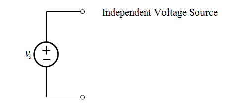
The Independent Voltage Source

An independent voltage source is characterised by a terminal voltage which is completely independent of the current through it. The representation of an independent voltage source is shown below:

Independent-Voltage-Source

If the value of the voltage source is constant, that is, does not change with time, then we can also represent it as an ideal battery:

Independent-Voltage-Source-circuit-ideal-battery

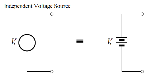
Although a “real” battery is not ideal, there are many circumstances under which an ideal battery is a very good approximation.

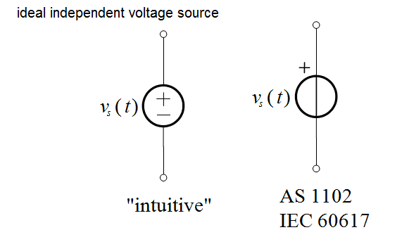
In general, however, the voltage produced by an ideal voltage source will be a function of time. In this case we represent the voltage symbolically as v(t ) .

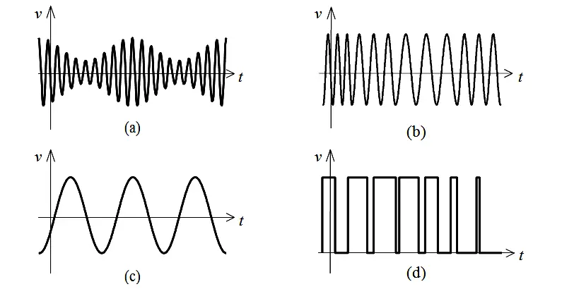
A few typical voltage waveforms are shown below. The waveforms in (a) and (b) are typical-looking amplitude modulation (AM) and frequency modulation (FM) signals, respectively. Both types of signals are used in consumer radio communications. The sinusoid shown in (c) has a wide variety of uses; for example, this is the shape of ordinary household voltage. A “pulse train”, such as that in (d), can be used to drive DC motors at a variable speed.

Source-Waveforms

Since the voltage produced by a source is in general a function of time, then the most general representation of an ideal voltage source is as shown below:

ideal-independent-voltage-source

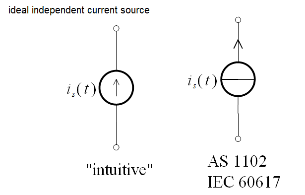
The Independent Current Source

An independent current source establishes a current which is independent of the voltage across it. The representation of an independent current source is shown below:

Independent-current-source

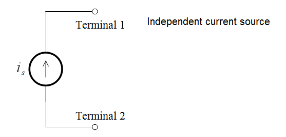
In other words, an ideal current source is a device that, when connected to anything, will always push current ( is) out of terminal 1 and pull is into terminal 2

Since the current produced by a source is in general a function of time, then the most general representation of an ideal current source is as shown below:

ideal-independent-current-source

Don't Miss Our Updates
Be the first to get exclusive content straight to your email.
We promise not to spam you. You can unsubscribe at any time.
Invalid email address
You've successfully subscribed !
Transistor as a Switch Working Principle
Full Wave Rectifier
N Type and P Type Semiconductors
Transistor Amplifier Working Principle
Electron Gun of Cathode Ray Tube
Share This Article
Facebook Whatsapp Whatsapp LinkedIn Copy Link
Share
Leave a Comment

Leave a Reply Cancel reply

Your email address will not be published. Required fields are marked *

Stay Connected

128.3kFollowersLike
69.1kFollowersFollow
208kSubscribersSubscribe
38kFollowersFollow

Categories

Recent Comments

  • Kamli on Top Free PLC Software
  • Guifty Shimica on Top Non-PLC Certification Courses for Automation Professionals
  • Guifty Shimica on Top Non-PLC Certification Courses for Automation Professionals
  • MIHARITSOA Aina Sitraka on Top Non-PLC Certification Courses for Automation Professionals

Related Articles

Transistor Voltage Divider Bias

Transistor Voltage Divider Bias

principle of time base generator

Time Base Generator

Capacitor Filter Operation

Capacitor Filter Operation

Transistor Emitter Feedback Bias

Transistor Emitter Feedback Bias

Combining Independent Voltage Sources in Series

Combining Independent Voltage Sources in Series

full-wave-bridge-rectifier-with-voltage-regulator

Basics of Voltage Regulators

Diode Rectifier

Bridge Rectifier Working Animation

Voltage Divider Rule

Voltage Divider Rule

More Articles

Types of Scan Time in a PLC

#16 PLC Best Practices – Create Trend for Cycle Time on HMI

Top 100 Zigbee Projects for Engineering Students

Top 100 Zigbee Projects for Engineering Students

Industrial Oven Control Application with PLC Controller

Industrial Oven Control Application with PLC Controller

Ladder Rung with Two Outputs

PLC Multiple Outputs Configuration

Pressure Measurement

How to Measure Pressure in Inches of Water Column

Shutdown Maintenance

The 5 Phases of Conducting Shutdown Maintenance

Logic Gates and Truth tables

Logic Gates and Truth tables

Accelerometer Vibration Probe

Accelerometer Vibration Probe Principle

Follow US
All rights reserved. Reproduction in whole or in part without written permission is prohibited.
Welcome Back!

Sign in to your account

Username or Email Address
Password

Lost your password?