Inst ToolsInst ToolsInst Tools
  • Courses
  • Automation
    • PLC
    • Control System
    • Safety System
    • Communication
    • Fire & Gas System
  • Instrumentation
    • Design
    • Pressure
    • Temperature
    • Flow
    • Level
    • Vibration
    • Analyzer
    • Control Valve
    • Switch
    • Calibration
    • Erection & Commissioning
  • Interview
    • Instrumentation
    • Electrical
    • Electronics
    • Practical
  • Q&A
    • Instrumentation
    • Control System
    • Electrical
    • Electronics
    • Analog Electronics
    • Digital Electronics
    • Power Electronics
    • Microprocessor
Search
  • Books
  • Software
  • Projects
  • Process
  • Tools
  • Basics
  • Formula
  • Power Plant
  • Root Cause Analysis
  • Electrical Basics
  • Animation
  • Standards
  • 4-20 mA Course
  • Siemens PLC Course
Reading: Specific Conductance Calibration Procedure
Share
Notification Show More
Font ResizerAa
Inst ToolsInst Tools
Font ResizerAa
  • Courses
  • Design
  • PLC
  • Interview
  • Control System
Search
  • Courses
  • Automation
    • PLC
    • Control System
    • Safety System
    • Communication
    • Fire & Gas System
  • Instrumentation
    • Design
    • Pressure
    • Temperature
    • Flow
    • Level
    • Vibration
    • Analyzer
    • Control Valve
    • Switch
    • Calibration
    • Erection & Commissioning
  • Interview
    • Instrumentation
    • Electrical
    • Electronics
    • Practical
  • Q&A
    • Instrumentation
    • Control System
    • Electrical
    • Electronics
    • Analog Electronics
    • Digital Electronics
    • Power Electronics
    • Microprocessor
Follow US
All rights reserved. Reproduction in whole or in part without written permission is prohibited.
Inst Tools > Blog > Analyzers > Specific Conductance Calibration Procedure

Specific Conductance Calibration Procedure

Last updated: September 14, 2016 11:00 pm
Editorial Staff
Analyzers Calibration
No Comments
Share
3 Min Read
SHARE

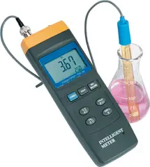
Conductivity is used to measure the ability of an aqueous solution to carry an electrical current. Specific conductance is the conductivity value corrected to 25 DC.

Most instruments are calibrated against a single standard which is near the specific conductance of the environmental samples. The standard can be either below or above the specific conductance of the environmental samples. A second standard is used to check the linearity of the instrument in the range of measurements.

When performing specific conductance measurement on groundwater or surface water and the measurement is outside the initial calibration range defined by the two standards, the instrument will need to be re-calibrated using the appropriate standards .

Specific Conductance Calibration Procedure:

1. Allow the calibration standards to equilibrate to the ambient temperature.

2. Fill calibration containers with the standards so each standard will cover the probe and temperature sensor. Remove probe from its storage container, rinse the probe with deionized water or a small amount of the standard (discard the rinsate), and’place the probe into the standard.

3. Select measurement mode. Wait ‘until the probe temperature has stabilized.

4. Select calibration mode, then specific conductance. Enter the specific conductance standard value. Make sure that the units on the standard are the same as the units used by the instrument. Ifnot, convert the units on the standard to the units used by the instrument.

5. Select measurement mode. The reading should remain within manufacturer’s specifications. If it does not, re-calibrate, If readings continue to change after re- calibration, consult manufacturer or replace calibration solution.

6. Remove probe from the standard, rinse the probe with deionized water or a small amount of the second standard (discard the rinsate), and place the probe into the second standard. The second standard will serve to verify the linearity of the instrument. Read the specific conductance value from the instrument and compare the value to the specific conductance on the standard. The two values should agree within the specifications of the instrument. If they do not agree, re-calibrate. If readings do not compare, then the second standard may be outside the linear range of the instrument. Use a standard that is closer to the first standard and repeat the verification. If values still do not compare, try cleaning the probe or consult the manufacturer.

7. After the calibration has been completed, rinse the probe with deionized water and store the probe according to manufacturer’s instructions.

8. Record the calibration information on calibration log sheet.

Note: for projects where specific conductance is not a critical measurement it may be possible to calibrate with one standard in the range of the expected measurement.
Don't Miss Our Updates
Be the first to get exclusive content straight to your email.
We promise not to spam you. You can unsubscribe at any time.
Invalid email address
You've successfully subscribed !

Continue Reading

Motor Operated Valve Functional Testing
Closed tank DP Level Transmitter with wet leg elevation zero remote mount Calibration
Dew Point Meter Principle
Hierarchy of Calibration Organizations
pH Transmitter Problem
Difference between Calibration and Ranging
Share This Article
Facebook Whatsapp Whatsapp LinkedIn Copy Link
Share
Leave a Comment

Leave a Reply Cancel reply

Your email address will not be published. Required fields are marked *

Stay Connected

128.3kFollowersLike
69.1kFollowersFollow
210kSubscribersSubscribe
38kFollowersFollow

Categories

Explore More

Calibration Procedure of Voltmeter and Ammeter
pH Monitoring System Triggers an Alarm
Instrument Zero and Span Calibration
Pressure Switch Calibration Procedure
Dispersive Spectroscopy
Gas Analyzers Interview Questions and Answers
Capacitance Level Switch Calibration
Smart Transmitter Calibration Tutorial Part 2

Keep Learning

Instrument Linearity Error

Instrument Errors – Zero, Span, Linearity

TOC Analyzer Principle

Total Organic Carbon Analyzer Principle

Pressure transmitter Calibration Setup

Instruments Calibration Procedures

Open-Tank-DP-Level-Transmitter-with-Zero-Suppression-Calibration

DP Level Transmitter with Zero Suppression Calibration

How to Calibrate Load Cells

How to Calibrate Load Cells in Weighing Applications?

thin-layer chromatography

Thin-Layer Chromatography : Manual Method

Total Organic Carbon Analyzers Questions and Answers

Total Organic Carbon Analyzers Questions and Answers

conductivity instruments

Four Electrode Conductivity Probes Principle

Learn More

Polyvinyl Alcohol in Oil Field

Polyvinyl Alcohol in Oil Field

hygrometer for measuring moisture

Difference Between Absolute and Relative Humidity

Ziegler-Nichols Open Loop Tuning Procedure

Ziegler-Nichols Open Loop Tuning Procedure

Symbol of Transistor

Power Transistor – Structure, Biasing, Characteristics, Advantages

L2F insertion-style flowmeter

Optical Flow Meter Principle

Analog Electronics Objective Questions

Analog Electronics Objective Questions – Set 4

Safety Instrumented Systems are different from Basic Process Control Systems

Safety Instrumented System Handbook – SIS Tutorials

Advantages & Disadvantages of AC power and DC power

Advantages & Disadvantages of AC power and DC power

Menu

  • About
  • Privacy Policy
  • Copyright

Quick Links

  • Learn PLC
  • Helping Hand
  • Part Time Job

YouTube Subscribe

Follow US
All rights reserved. Reproduction in whole or in part without written permission is prohibited.
Welcome Back!

Sign in to your account

Username or Email Address
Password

Lost your password?