This article provides information on Zero Suppression and Zero Elevation Calculations used in differential pressure level transmitter.
What is Zero Suppression ?
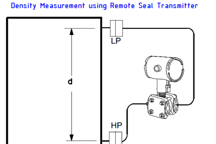
In some cases, the level transmitter has to be mounted X meters below the base of an open tank as shown in below figure.

The liquid in the high pressure impulse line exerts a constant pressure (P = S . X) on the high pressure side.
That is, the pressure on the high pressure side of the DP Transmitter is always higher than the actual pressure exerted by the liquid column in the tank by (SG . X) – so the reading will be in error high.
This constant pressure would cause an output signal that is higher than 4 mA when the tank is empty and above 20 mA when it is full.
When the liquid level is at H meters, pressure on the high pressure side of the transmitter will be:
Phigh = S·H + S.X + Patm
Plow= Patm
ΔP = Phigh – Plow = S . H + S . X
The transmitter has to be negatively biased by a value of S.X so that the output of the transmitter is proportional to the tank level (S . H) only.
The above procedure is called Zero Suppression and it can be done during calibration of the transmitter.
What is Zero Elevation ?
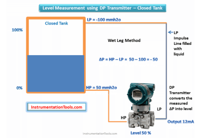
When a wet leg installation is used,the low pressure side of the level transmitter will always experience a higher hydrostatic pressure than the high pressure side.
This is due to the fact that the height of the wet leg (X) is always just greater than the maximum height of the liquid column (H) inside the tank.

When the liquid level is at H meters, we have:
Phigh =Pgas + S . H
Plow =Pgas + S . X
ΔP = Phigh – Plow = S . H – S . X = -S(X . H)
The differential pressure ΔP sensed by the transmitter is always a negative value (i.e. the low pressure side has a higher pressure than high pressure side).
To properly calibrate the transmitter, a positive bias (S . X) is needed to elevate the transmitter output.
This positive biasing technique is called zero elevation.
Zero Suppression and Zero Elevation Example Calculation
Zero suppression calculation

Span = (x) (GL)
HW at minimum level = (z) (GS) + (y) (GL)
HW at maximum level = (z) (GS) + (x + y) (GL)
Where
GL = Specific gravity of tank liquid
GS = Specific gravity of seal liquid
HW = Equivalent head of water
x, y, and z as shown in above figure
Example:
Open tank with x = 80 inches
y = 5 inches
z = 10 inches
GL = 0.8
GS = 0.9
Span = (80)(0.8) = 64 inches
HW at minimum level = (10)(0.9) + (5)(0.8) = 13 inches
HW at maximum level = (10)(0.9) + (5 + 80)(0.8) = 77 inches
Calibrated Range = 13 to 77 inches head of water
Zero elevation calculation Closed Tank With Wet Leg

Span = (x)(GL) Wet Leg
HW at minimum level = (y)(GL) – (d)(GS)
HW at maximum level = (x + y)(GL) – (d)(GS)
Where
GL = Specific gravity of tank liquid
GS = Specific gravity of seal liquid
HW = Equivalent head of water
Example:
Closed tank with x = 70 inches y = 20 inches, and d = 100 inches, GL = 0.8 Seal Liquid, GS = 0.9
Span = (70)(0.8) = 56 inches
HW at minimum level = (20)(0.8) – (100)(0.9) = -74 inches
HW at maximum level = (70 + 20)(0.8) – (100)(0.9) = -18 inches
Calibrated Range = -74 to -18 inches head of water
(Minus signs indicate that the higher pressure is applied to the low pressure side of the transmitter.)
Articles You May Like :
Level Transmitter Compensation
Field Instrumentation Questions
Remote mount Level Transmitter


. I am very thankful to you sir. Thanks for explaining about Zero Suppression and Zero Elevation.
How about explaining how to calculate zero suppression and zero elevation when the level transmitter is above a closed tank and the upper head space is pressurized at 30 psig with air? This is one of the common uses for remote water level monitoring of the seal pots/tanks for the process pump seals.
Thanks sir
Thank you Sir for all your best Information to sharing us
Thanks you sir
Why we used upperline high in drum level or dearetor level
Thannks for refreshing the theory
What is Zero Elevation?
The H in the related figure is wrong from the formula Phigh =Pgas + S . H.
As per the formula H base line should be from the Transmitter datum line,( NOT from the tank bottom).
Kindly clarify some one how y came here, how y came and previous level calculation is differ kindly tell me.
Thank you so much for explaining this topic,this is very beneficial article for learning.