Inst ToolsInst ToolsInst Tools
  • Courses
  • Automation
    • PLC
    • Control System
    • Safety System
    • Communication
    • Fire & Gas System
  • Instrumentation
    • Design
    • Pressure
    • Temperature
    • Flow
    • Level
    • Vibration
    • Analyzer
    • Control Valve
    • Switch
    • Calibration
    • Erection & Commissioning
  • Interview
    • Instrumentation
    • Electrical
    • Electronics
    • Practical
  • Q&A
    • Instrumentation
    • Control System
    • Electrical
    • Electronics
    • Analog Electronics
    • Digital Electronics
    • Power Electronics
    • Microprocessor
  • Request
Search
  • Books
  • Software
  • Projects
  • Process
  • Tools
  • Basics
  • Formula
  • Power Plant
  • Root Cause Analysis
  • Electrical Basics
  • Animation
  • Standards
  • 4-20 mA Course
  • Siemens PLC Course
Reading: Why CT Secondary Should Never Be Kept Open?
Share
Font ResizerAa
Inst ToolsInst Tools
Font ResizerAa
  • Courses
  • Design
  • PLC
  • Interview
  • Control System
Search
  • Courses
  • Automation
    • PLC
    • Control System
    • Safety System
    • Communication
    • Fire & Gas System
  • Instrumentation
    • Design
    • Pressure
    • Temperature
    • Flow
    • Level
    • Vibration
    • Analyzer
    • Control Valve
    • Switch
    • Calibration
    • Erection & Commissioning
  • Interview
    • Instrumentation
    • Electrical
    • Electronics
    • Practical
  • Q&A
    • Instrumentation
    • Control System
    • Electrical
    • Electronics
    • Analog Electronics
    • Digital Electronics
    • Power Electronics
    • Microprocessor
  • Request
Follow US
All rights reserved. Reproduction in whole or in part without written permission is prohibited.
Inst Tools > Blog > Electrical Basics > Why CT Secondary Should Never Be Kept Open?

Why CT Secondary Should Never Be Kept Open?

Learn why CT secondary should never be kept open to ensure accurate measurements and optimal protection in electrical circuits.

Last updated: March 16, 2025 4:38 pm
Viral Nagda
Electrical Basics
No Comments
Share
6 Min Read
SHARE

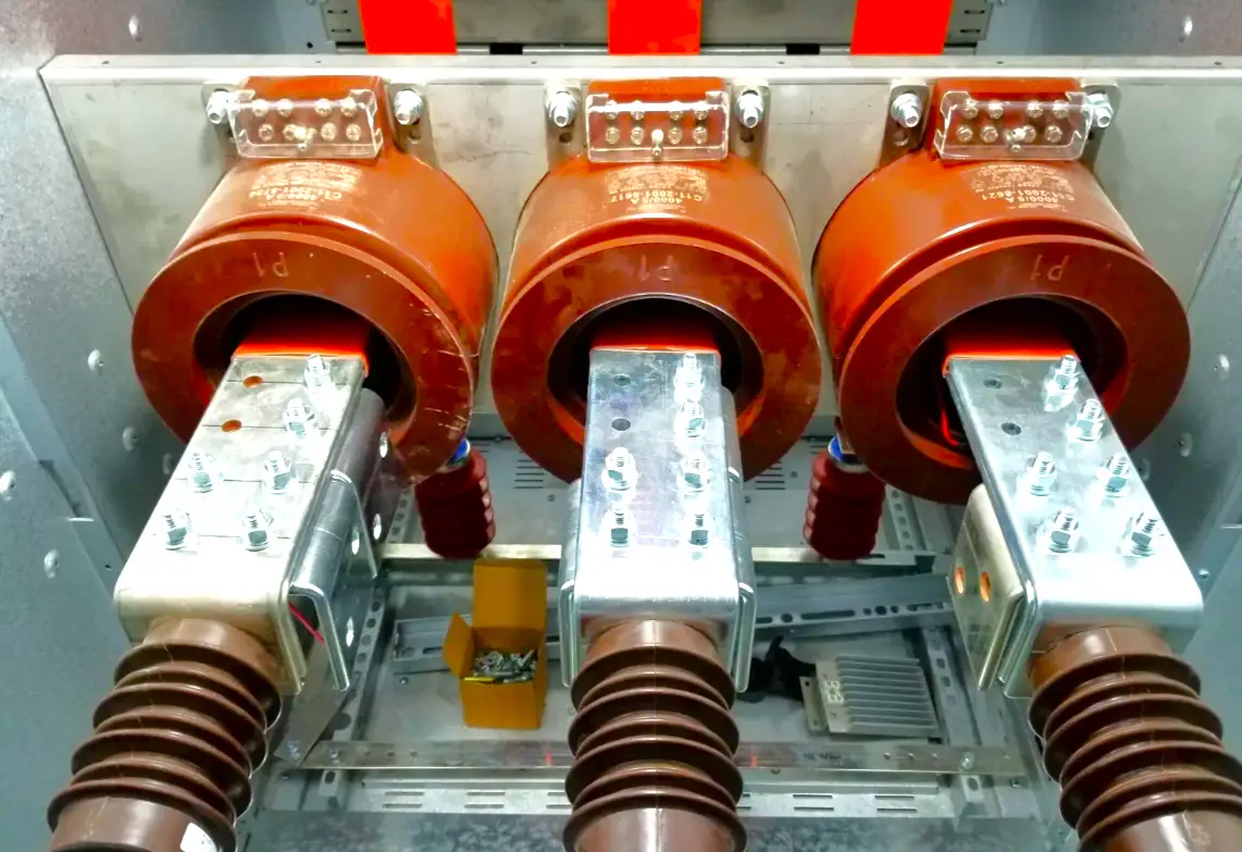
We all know how a CT or current transformer plays a very important role in electrical circuits. It can be used to either measure electrical parameters like current and all, or used as a protection CT to protect electrical circuits by detecting fault current. As CT is a transformer having primary and secondary windings, many engineers sometimes ignore the importance of secondary winding always being connected. In this post, we will see why CT secondary winding should never be kept open.

Contents
What is the use of current transformers in electrical circuits?What happens when the secondary CT is open-circuited?

What is the use of current transformers in electrical circuits?

Current transformers are useful in electrical engineering, as they can serve dual purpose – either as a metering CT or protection CT. In the case of metering CT, it acts as a step-down transformer, where the secondary voltage is reduced to a great extent. This reduced voltage is then used to feed energy meters, and then they further measure electrical parameters corresponding to the current flowing in the primary winding.

In the case of protection CT, it usually acts as a step-up transformer, where it is designed to carry higher fault currents. The secondary winding of protection CT is connected to protection relays, which open the circuit in case of fault currents. Due to this, the electrical circuit is prevented from any damage.

Why CT Secondary Should Never Be Kept Open?

What happens when the secondary CT is open-circuited?

First of all, let us understand how secondary winding gets its voltage and the behavior of current in case of load connected. As the transformer works on the electromagnetic induction principle, voltage present in the primary winding creates a magnetic field in the core (area between primary and secondary), which in turn creates magnetic flux. This magnetic flux is responsible for inducing a voltage in the secondary winding.

The flux generated by the primary current is called primary flux and will flow in the direction of the secondary winding. Now, as the voltage is induced in the secondary winding and if current flows through it due to the load connected, then that too will create a magnetic flux and this flux will now be called secondary flux. Secondary flux will flow in the direction of the primary winding.

As both the windings are connected opposite to each other, the flux generated too is clashing with each other, as one is going left and the other is going right. This ultimately gives rise to net flux (primary – secondary), as they are opposite in nature. The net flux will always be less than the primary flux or secondary flux.

Remember one thing that in CT, the primary winding does not care whether the load is connected to the secondary winding or not; this is not the case in a regular transformer. The current flowing in the secondary will affect the current flowing in the primary winding by some factor. So, irrespective of whether you have a connected load or not on the secondary side, the primary current will be maintained throughout in the case of the current transformer.

Now, coming back to our case, the circuit is healthy if load is connected in the secondary winding, as it will allow secondary flux to be generated and reduce the net flux overall. If net flux is low, then even a high voltage at primary cannot affect the secondary winding performance, because it is also generating a corresponding flux and cutting the net result.

But what happens if the load is not connected? As net flux is the difference between primary flux and secondary flux, and as there is no load, the secondary flux will be zero. In that case, the net flux will be equal to the primary flux. Now, this means that as the flux is responsible for inducing a voltage in secondary winding as discussed before, the primary voltage will now try to induce its full force in the secondary winding.

Due to this, the voltage present on the secondary side will be very high or at least equal to the primary voltage, which can be determined by the following expression: VS = 4.44 * net flux * F * NS, where VS is secondary voltage, F is the frequency of primary current and NS is secondary winding turns.

CT secondary is designed to operate under a normal rated voltage range, and such a high voltage across it can damage its windings due to core saturation. Such a high voltage induced and the circuit being open, no one will know and can thus pose a high risk of electric shock or a nasty accident. Also, due to this high abnormal voltage, heat dissipation will increase and can thus try to damage the windings more quickly. A fire hazard can also occur due to such reasons.

In this way, we saw why CT secondary should never be kept open.

Read Next:

  • What are Switchgear Interlocks?
  • What is an Automatic Circuit Recloser?
  • What is the LBB Protection Relay?
  • Difference Between AIS and GIS Panel
  • High-Voltage Testing in Electrical Panels
Don't Miss Our Updates
Be the first to get exclusive content straight to your email.
We promise not to spam you. You can unsubscribe at any time.
Invalid email address
You've successfully subscribed !

Continue Reading

Difference Between Single Core and Multi-Core Cables
Types of Electrical Loads
What is Arc Protective Clothing? – Importance, Features, Materials
What is a Megger? Principle, Advantages, Disadvantages, Applications
Testing and Inspection of Bonding and Grounding Systems
What is a Relay? Types of Industrial Relays
Share This Article
Facebook Whatsapp Whatsapp LinkedIn Copy Link
Share
Leave a Comment

Leave a Reply Cancel reply

Your email address will not be published. Required fields are marked *

Stay Connected

128.3kFollowersLike
69.1kFollowersFollow
210kSubscribersSubscribe
38kFollowersFollow

Categories

Explore More

Difference Between MCB and MCCB
Things to Know When Measuring Current
Effects of Long Distance Cables between VFD and Motor
Stepper Motor Working Principle
What is a Capacitor Bank?
Automatic Motor Forward and Reverse Control using Timer
Electrical Drives – Modes, Types, Speed Control Applications
What is a Buchholz Relay? Working Principle

Keep Learning

How to Read and Understand an Electrical Single Line Diagram?

How to Read and Understand an Electrical Single Line Diagram?

How to Check the Continuity of Protective Conductors

How to Check the Continuity of Protective Conductors?

Star and Delta Wiring Animation

Basics of Star and Delta connections

Difference Between NEMA and IEC Motors

Difference Between NEMA and IEC Motors?

Industrial Star Delta Starter for 3-Phase Induction Motor

Star Delta Starter – Working, Circuit, Advantages, Disadvantages

Difference between Stepper Motor and Servo Motor

Difference Between Earth and Neutral

Difference Between Earth and Neutral

Difference Between Permittivity and Permeability

Difference Between Permittivity and Permeability

Learn More

Power Electronics Objective Questions

IGBT Quiz

Thermocouple Questions and Answers

Thermocouple Questions and Answers

Time Response Analysis

Time Response of Second Order Systems – II

Tips to Maintain & Extend the Life of CNC Tools

Tips for Maintaining and Extending the Life of Your CNC Tools

Structured Text PLC Program for Sequential Process Data Storage

Structured Text PLC Code for Sequential Process Data Storage

Level Measurement Objective Questions

Level Measurement Objective Questions

Heat Recovery in HVAC System

Heat Recovery in HVAC System

Calculate Power in Series RC Circuit

Calculate Power in Series RC Circuit

Menu

  • About
  • Privacy Policy
  • Copyright

Quick Links

  • Learn PLC
  • Helping Hand
  • Part Time Job

YouTube Subscribe

Follow US
All rights reserved. Reproduction in whole or in part without written permission is prohibited.
Welcome Back!

Sign in to your account

Username or Email Address
Password

Lost your password?