Inst ToolsInst ToolsInst Tools
  • Courses
  • Automation
    • PLC
    • Control System
    • Safety System
    • Communication
    • Fire & Gas System
  • Instrumentation
    • Design
    • Pressure
    • Temperature
    • Flow
    • Level
    • Vibration
    • Analyzer
    • Control Valve
    • Switch
    • Calibration
    • Erection & Commissioning
  • Interview
    • Instrumentation
    • Electrical
    • Electronics
    • Practical
  • Q&A
    • Instrumentation
    • Control System
    • Electrical
    • Electronics
    • Analog Electronics
    • Digital Electronics
    • Power Electronics
    • Microprocessor
  • Request
Search
  • Books
  • Software
  • Projects
  • Process
  • Tools
  • Basics
  • Formula
  • Power Plant
  • Root Cause Analysis
  • Electrical Basics
  • Animation
  • Standards
  • 4-20 mA Course
  • Siemens PLC Course
Reading: What is Contactor ?
Share
Font ResizerAa
Inst ToolsInst Tools
Font ResizerAa
  • Courses
  • Design
  • PLC
  • Interview
  • Control System
Search
  • Courses
  • Automation
    • PLC
    • Control System
    • Safety System
    • Communication
    • Fire & Gas System
  • Instrumentation
    • Design
    • Pressure
    • Temperature
    • Flow
    • Level
    • Vibration
    • Analyzer
    • Control Valve
    • Switch
    • Calibration
    • Erection & Commissioning
  • Interview
    • Instrumentation
    • Electrical
    • Electronics
    • Practical
  • Q&A
    • Instrumentation
    • Control System
    • Electrical
    • Electronics
    • Analog Electronics
    • Digital Electronics
    • Power Electronics
    • Microprocessor
  • Request
Follow US
All rights reserved. Reproduction in whole or in part without written permission is prohibited.
Inst Tools > Blog > Electronic Basics > What is Contactor ?

What is Contactor ?

Last updated: July 4, 2019 7:18 am
Editorial Staff
Electronic Basics How It Works
1 Comment
Share
4 Min Read
SHARE

To start up and shut down a three-phase AC induction motor, any three-pole switch with a suitable current rating will suffice.

Simply closing such a switch to send three-phase power to the motor will cause it to start up, while opening the three-pole switch will cut power to the motor to make it turn off.

If we desire to have remote start and stop control over a three-phase motor, we need a special relay with switch contacts big enough to safely conduct the motor’s inrush current over many start and stop cycles.

Large, high-current-rated electromechanical relays built for this very purpose are commonly referred to as contactors in industry.

A schematic diagram of a three-phase contactor connected to a three-phase motor (with fuses for overcurrent protection) is shown here:

Motor contactors

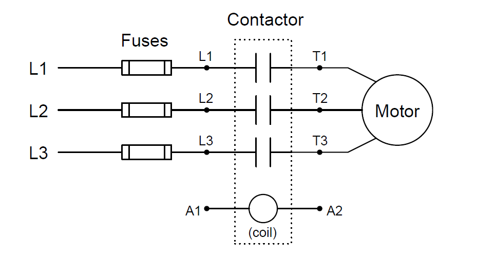
Energizing terminals A1 and A2 magnetizes the electromagnet coil, causing all three switch contacts to simultaneously close, sending three-phase AC power to the motor.

De-energizing the coil causes it to de-magnetize, releasing the armature and enabling a return spring inside the contactor to snap all three contacts to the open (off) position.

A contactor rated at 75 horsepower (at 480 volt AC 3-phase power) is shown here, both assembled and with the top cover removed to reveal the three sets of high-current electrical switch contacts:

Motor Contactors Images

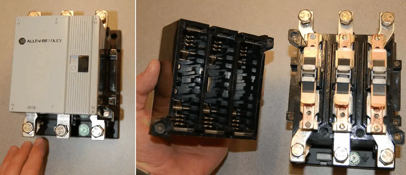
Each phase switch contact is actually a series pair of contacts that make and break simultaneously with the actuation of a ferrous armature attracted by an electromagnet coil in the base of the contactor assembly.

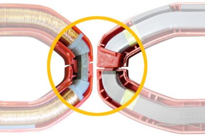
The operation of the three contact sets may be seen in this pair of photographs, the left-hand image showing the contacts in their normal (open) state, and the right-hand image showing the contacts closed (the armature “pulled in”) by the force of my finger:

Contactors Contacts

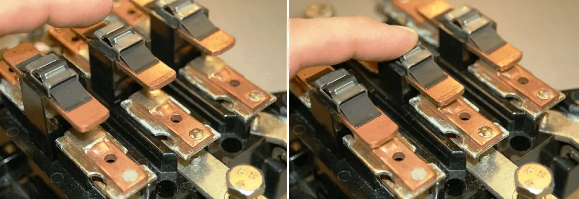
Of course, it would be very dangerous to touch or manually actuate the contacts of a motor starting relay with the cover removed as shown.

Not only would there be an electric shock hazard from touching any one of the bare copper contacts with your finger, but the arcing produced by closing and opening such contacts would pose arc flash and arc blast hazards. This is why all modern motor contactors are equipped with arc shield covers.

The actual switch contact pads are not made of pure copper, but rather silver (or a silver alloy) designed to survive the repeated arcing and blasting action of large AC currents being initiated and interrupted.

Below the main power connection terminals (L1-L3, T1-T3) on this contactor hide two small screw terminals (commonly denoted A1 and A2) providing connection points to the electromagnet coil actuating the contactor:

Contactors Connections

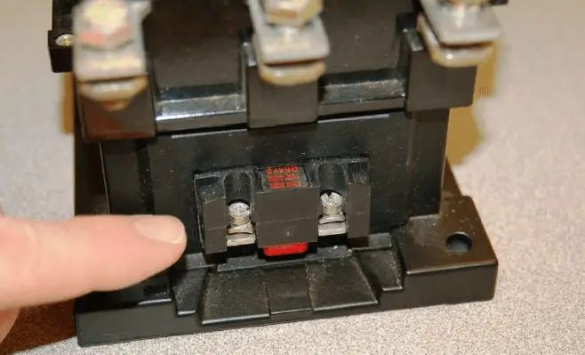
Like most three-phase contactors, this one’s coil is rated for 120 volts AC. Although the electric motor may operate on three-phase, 480 volt AC power, the contactor coil and the rest of the control circuitry operates on a lower voltage for reasons of safety.

Like all electromechanical relays, motor contactors use a low-power signal to control higher-power electric current to the load.

This “amplifying” action enables relatively small control switches, PLCs, and relay circuits to start and stop relatively large (high-current) electric motors.

Credits : by Tony R. Kuphaldt – under the terms and conditions of the Creative Commons Attribution 4.0 License

Don't Miss Our Updates
Be the first to get exclusive content straight to your email.
We promise not to spam you. You can unsubscribe at any time.
Invalid email address
You've successfully subscribed !

Continue Reading

Dead Weight Tester Working Animation
What is an Electrical Wire Mesh?
Difference Between LED and LDR
How to Test a Transistor using Multimeter
Ultrasonic Level Transmitter Animation
What is a Fuse ?
Share This Article
Facebook Whatsapp Whatsapp LinkedIn Copy Link
Share
1 Comment
  • Luis Perez says:
    January 16, 2019 at 10:13 pm

    Excellent info!!!

    Reply

Leave a Reply Cancel reply

Your email address will not be published. Required fields are marked *

Stay Connected

128.3kFollowersLike
69.1kFollowersFollow
210kSubscribersSubscribe
38kFollowersFollow

Categories

Explore More

How to Measure AC Voltage using Multimeter
Magnetic Level Indicators Working Animation
Float Level Switch Working Principle
How to Test a Diode using Multimeter
Paddle Wheel Flow Meters – Principle, Advantages, Limitations
Difference Between Electrical and Electronic Devices
Types of Potentiometers – What is a Potentiometer? – Applications
Power Supply Circuit Fault Analysis

Keep Learning

How are Silicon Chips Disposed?

How are Silicon Chips Disposed?

Impeller Flow Sensor

Impeller Flow Sensor Working Principle and Animation

Difference Between LDR and Photodiode

Difference Between LDR and Photodiode

Difference Between Clamp Meters and Digital Multimeters

Difference Between Clamp Meters and Multimeters

Catalytic-Bead-Sensor-2

Gas Detectors Working Principle

How to Use SMD Components in Electronic Circuits

How to Use SMD Components in Electronic Circuits?

Voltage Regulator Circuit

Basics of Voltage Regulator

Top Beginner Soldering Mistakes

Top Beginner Soldering Mistakes and How to Avoid Them?

Learn More

Digital Control Systems

Z & S Domain Relationship

RAID stands for Redundant Array of Independent Disks

What is Raid Parity? – Types, Advantages, Disadvantages

Electronic Devices & Circuits Objective Questions

Electronic Devices & Circuits Quiz – Set 14

Modbus Simulator Softwares

Flame Detectors Working Principle

Flame Detectors Working Principle

Instrumentation Documents

Instrument Document Quiz

Differential Pressure Measurement across Baghouse

Differential Pressure Measurement across Baghouse

Modbus ASCII and RTU Message Frame

Background of Modbus – ASCII and RTU Data Frames

Menu

  • About
  • Privacy Policy
  • Copyright

Quick Links

  • Learn PLC
  • Helping Hand
  • Part Time Job

YouTube Subscribe

Follow US
All rights reserved. Reproduction in whole or in part without written permission is prohibited.
Welcome Back!

Sign in to your account

Username or Email Address
Password

Lost your password?