Inst ToolsInst ToolsInst Tools
  • Courses
  • Automation
    • PLC
    • Control System
    • Safety System
    • Communication
    • Fire & Gas System
  • Instrumentation
    • Design
    • Pressure
    • Temperature
    • Flow
    • Level
    • Vibration
    • Analyzer
    • Control Valve
    • Switch
    • Calibration
    • Erection & Commissioning
  • Interview
    • Instrumentation
    • Electrical
    • Electronics
    • Practical
  • Q&A
    • Instrumentation
    • Control System
    • Electrical
    • Electronics
    • Analog Electronics
    • Digital Electronics
    • Power Electronics
    • Microprocessor
  • Request
Search
  • Books
  • Software
  • Projects
  • Process
  • Tools
  • Basics
  • Formula
  • Power Plant
  • Root Cause Analysis
  • Electrical Basics
  • Animation
  • Standards
  • 4-20 mA Course
  • Siemens PLC Course
Reading: What is Cathode Ray oscilloscope ?
Share
Font ResizerAa
Inst ToolsInst Tools
Font ResizerAa
  • Courses
  • Design
  • PLC
  • Interview
  • Control System
Search
  • Courses
  • Automation
    • PLC
    • Control System
    • Safety System
    • Communication
    • Fire & Gas System
  • Instrumentation
    • Design
    • Pressure
    • Temperature
    • Flow
    • Level
    • Vibration
    • Analyzer
    • Control Valve
    • Switch
    • Calibration
    • Erection & Commissioning
  • Interview
    • Instrumentation
    • Electrical
    • Electronics
    • Practical
  • Q&A
    • Instrumentation
    • Control System
    • Electrical
    • Electronics
    • Analog Electronics
    • Digital Electronics
    • Power Electronics
    • Microprocessor
  • Request
Follow US
All rights reserved. Reproduction in whole or in part without written permission is prohibited.
Inst Tools > Blog > Electronic Basics > What is Cathode Ray oscilloscope ?

What is Cathode Ray oscilloscope ?

Last updated: June 8, 2018 1:32 pm
Editorial Staff
Electronic Basics
No Comments
Share
3 Min Read
SHARE

In studying the various electronic, electrical networks and systems, signals which are functions of time, are often encountered. Such signals may be periodic or non-periodic in nature. The device which allows, the amplitude of such signals, to be displayed primarily as a function of time is called cathode ray oscilloscope, commonly known as CRO. The C.R.O gives the Visual representation of the time varying signals. The oscilloscope has become an universal instrument and is probably most versatile tool for the development of electronic circuits and systems. It is an integral part of electronic laboratories.

What is Oscilloscope

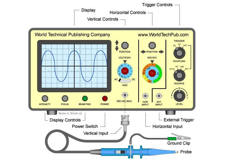
The oscilloscope is, in fact, a voltmeter. Yes, you read it right. It is in fact, a voltmeter. Instead of the mechanical deflection of a metallic pointer as used in the normal voltmeters, the oscilloscope uses the movement of a visible spot. The movement of such spot on the screen is proportional to the varying magnitude of the signal, which is under measurement.

The electron beam can be deflected in two directions: the horizontal or x-direction and the vertical or y-direction. Thus an electron beam producing a spot can be used to produce two dimensional displays. Thus C.R.O can be regarded as a fast x-y plotter. The x-axis and y-axis can be used study the variation of one voltage as a function of another.


Typically the x-axis of the oscilloscope represents the time while the y-axis represents variation of the input voltage signal. Thus if the input voltage signal applied to the y-axis of C.R.O is sinusoidally varying and if x-axis represents the time axis, then the spot moves sinusoidally, and the familiar sinusoidal waveform can be seen on the screen of the oscilloscope. The oscilloscope is so fast device that it can display the periodic signals whose time period is as small as microseconds and even nanoseconds. The C.R.O basically operates on voltages, but it is possible to convert current, pressure, strain, acceleration and other physical quantities into the voltage using transducers and obtain their visual representations on the C.R.O.

Don't Miss Our Updates
Be the first to get exclusive content straight to your email.
We promise not to spam you. You can unsubscribe at any time.
Invalid email address
You've successfully subscribed !

Continue Reading

How does SMPS Works? – Switched Mode Power Supply
How to Measure capacitance using Multimeter
Electrical Static Grounding Techniques
How to Test a Transistor using Multimeter
Power Supply Circuit Fault Analysis
Basics of Voltage Regulator
Share This Article
Facebook Whatsapp Whatsapp LinkedIn Copy Link
Share
Leave a Comment

Leave a Reply Cancel reply

Your email address will not be published. Required fields are marked *

Stay Connected

128.3kFollowersLike
69.1kFollowersFollow
210kSubscribersSubscribe
38kFollowersFollow

Categories

Explore More

100 Electronics and Electrical Projects for Engineering Students
How to Test a Battery using a Multimeter?
What is an Inductor? – Types of Inductors
Types of Noise in Electronics
What is an Electrical Wire Mesh?
NO vs NC Contact
How a Transistor Switch Works
Factors Affecting Inductance

Keep Learning

Testing a defective transistor

Testing a Transistor with a Digital Multimeter

What is PCB Corrosion - Electronic Boards Corrosion Prevention

What is PCB Corrosion? Electronic Boards Corrosion Prevention

Difference of Energy Gap

Difference between Intrinsic and Extrinsic Semiconductors

Clamp Meter

What is a Clamp Meter?

Measure Frequency using Multimeter

How to measure frequency using Multimeter

Motor contactors

What is Contactor ?

Difference Between Electrical and Electronic Devices

Difference Between Electrical and Electronic Devices

Diode-testing-with-multimeter

How to Test a Diode using Multimeter

Learn More

valve packing assembly

What is Valve Packing ?

Client - server network system

Network Operating System

Image Processing Projects for Engineering Students

Image Processing Projects for Engineering Students

Stability in Frequency Domain

Closed-Loop Frequency Response

Hysteresis - 2

Hysteresis

Frequency Measurement Objective Questions

Frequency Measurement Objective Questions

Electric Motor Animation

Electric Motor Working Animation

Overview of Industrial Control Systems

Overview of Industrial Control Systems

Menu

  • About
  • Privacy Policy
  • Copyright

Quick Links

  • Learn PLC
  • Helping Hand
  • Part Time Job

YouTube Subscribe

Follow US
All rights reserved. Reproduction in whole or in part without written permission is prohibited.
Welcome Back!

Sign in to your account

Username or Email Address
Password

Lost your password?