What is an O-Ring?
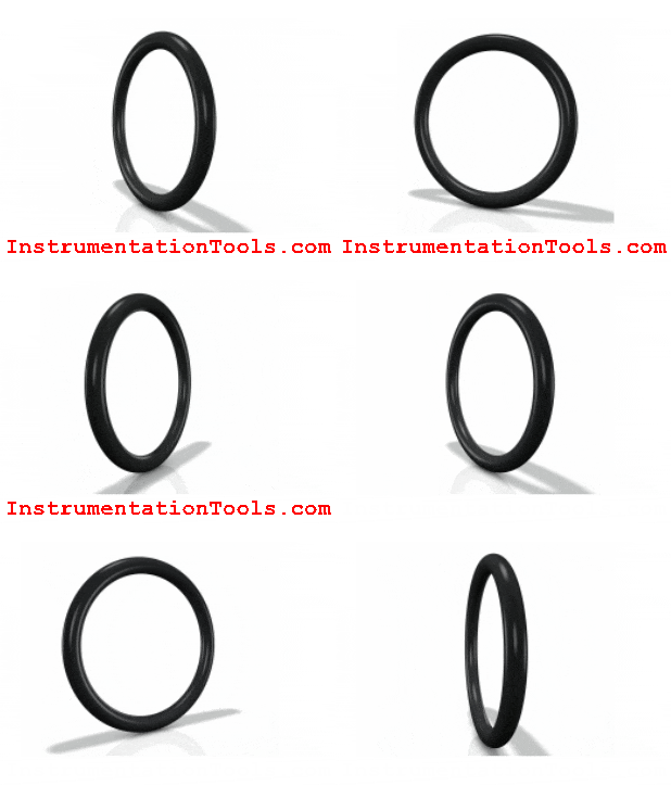
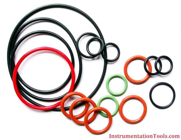
An O-ring is a torus, or doughnut-shaped ring, generally molded from an elastomer, although O-rings are also made from PTFE and other thermoplastic materials, as well as metals, both hollow and solid.
O-rings are used primarily for sealing.
An O-ring, also known as a packing, or a toric joint, is a mechanical gasket in the shape of a torus; it is a loop of elastomer with a round cross-section, designed to be seated in a groove and compressed during assembly between two or more parts, creating a seal at the interface.
The O-ring may be used in static applications or in dynamic applications where there is relative motion between the parts and the O-ring. Dynamic examples include rotating pump shafts and hydraulic cylinder pistons.
O-rings are one of the most common seals used in machine design because they are inexpensive, easy to make, and reliable and have simple mounting requirements. They can seal tens of megapascals (thousands of psi) of pressure.
What is an O-Ring Seal?
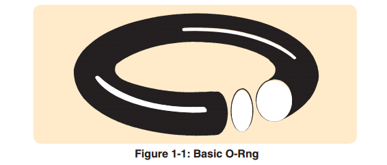
An O-ring seal is used to prevent the loss of a fluid or gas. The seal assembly consists of an elastomer O-ring and a gland. An O-ring is a circular cross-section ring molded from rubber (Figure 1-1).
The gland — usually cut into metal or another rigid material — contains and supports the O-ring (Figures 1-2 and 1-3). The combination of these two elements; O-ring and gland — constitute the classic O-ring seal assembly.
Advantages of O-Rings
- They seal over a wide range of pressure, temperature and tolerance.
- Ease of service, no smearing or retightening.
- No critical torque on tightening, therefore unlikely to cause structural damage.
- O-rings normally require very little room and are light in weight.
- In many cases an O-ring can be reused, an advantage over non-elastic fl at seals and crush-type gaskets.
- The duration of life in the correct application corresponds to the normal aging period of the O-ring material.
- O-ring failure is normally gradual and easily identified.
- Where differing amounts of compression effect the seal function (as with fl at gaskets), an O-ring is not effected because metal to metal contact is generally allowed for.
- They are cost-effective.
Operation :
All robust seals are characterized by the absence of any pathway by which fluid or gas might escape. Detail differences exist in the manner by which zero clearance is obtained
— welding, brazing, soldering, ground fits or lapped finishes
— or the yielding of a softer material wholly or partially confined between two harder and stiffer members of the assembly. The O-ring seal falls in the latter class.
The rubber seal should be considered as essentially an incompressible, viscous fluid having a very high surface tension. Whether by mechanical pressure from the surrounding structure or by pressure transmitted through hydraulic fluid, this extremely viscous fluid is forced to flow within the gland to produce “zero clearance” or block to the flow of the less viscous fluid being sealed.
The rubber absorbs the stack-up of tolerances of the unit and its internal memory maintains the sealed condition.
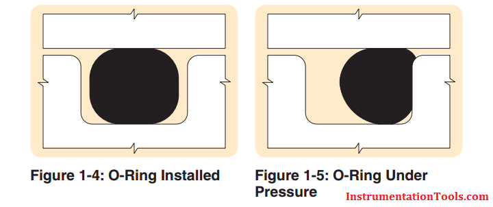
Figure 1-4 illustrates the O-ring as installed, before the application of pressure. Note that the O-ring is mechanically squeezed out of round between the outer and inner members to close the fluid passage. The seal material under mechanical pressure extrudes into the microfine grooves of the gland.
Figure 1-5 illustrates the application of fluid pressure on the O-ring. Note that the O-ring has been forced to flow up to, but not into, the narrow gap between the mating surfaces and in so doing, has gained greater area and force of sealing contact.
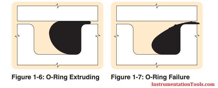
Figure 1-6 shows the O-ring at its pressure limit with a small portion of the seal material entering the narrow gap between inner and outer members of the gland.
Figure 1-7 illustrates the result of further increasing pressure and the resulting extrusion failure. The surface tension of the elastomer is no longer sufficient to resist fl ow and the material extrudes (flows) into the open passage or clearance gap.
O-Ring Characteristics
A very early and historically prominent user of O-rings(1) cites a number of characteristics of O-ring seals which are still of interest to seal designers. Extracts of the more general characteristics are listed as follows:
A. The seals can be made perfectly leak-proof for cases of static pistons and cylinders for fl uid pressures up to 5000 psi. (Limit of test pressure). The pressure may be constant or variable.
B. The seals can be made to seal satisfactorily between reciprocating pistons and cylinders at any fluid pressure up to 5000 psi.
There may be slight running leakage (a few drops per hundred strokes) depending on the filmforming ability of the hydraulic medium. O-rings can be used between rotating members with similar results but in all cases the surface rubbing speed must be kept low.
C. A single O-ring will seal with pressure applied alternately on one side and then on the other, but in cases of severe loading or usage under necessarily unfavorable conditions, seal life can be extended by designing the mechanism so that each seal is subjected to pressure in one direction only.
Seals may be arranged in series as a safety measure but the fi rst seal exposed to pressure will take the full load.
D. O-ring seals must be radially compressed between the bottom of the seal groove and the cylinder wall for proper sealing action.
This compression may cause the seal to roll slightly in its groove under certain conditions of piston motion, but the rolling action is not necessary for normal operation of the seals.
E. In either static or dynamic O-ring seals under high pressure the primary cause of seal failure is extrusion of the seal material into the piston-cylinder clearance.
The major factors effecting extrusion are fl uid pressure, seal hardness and strength, and piston-cylinder clearance.
F. Dynamic seals may fail by abrasion against the cylinder or piston walls. Therefore, the contacting surfaces should be polished for long seal life.
Moving seals that pass over ports or surface irregularities while under hydraulic pressure are very quickly cut or worn to failure.
G. The shape of the seal groove is unimportant as long as it results in proper compression of the seal between the bottom of the groove and the cylinder wall, and provides room for the compressed material to flow so that the seal is not solidly confined between metal surfaces.
H. The seal may be housed in a groove cut in the cylinder wall instead of on the piston surface without any change in design limitations or seal performance.
I. Friction of moving O-ring seals depends primarily on seal compression, fluid pressure, and projected seal area exposed to pressure. The effects of materials, surfaces, fluids, and speeds of motion are normally of secondary importance, although these variables have not been completely investigated.
Friction of O-ring seals under low pressures may exceed the friction of properly designed lip type seals, but at higher pressures, developed friction compares favorably with, and is often less than, the friction of equivalent lip type seals.
J. The effects of temperature changes from +18°C to +121°C (-65°F to +250°F) on the performance of O-ring seals depends upon the seal material used. Synthetic rubber can be made for continual use at high or low temperatures, or for occasional short exposure to wide variations in temperature.
At extremely low temperature the seals may become brittle but will resume their normal flexibility without harm when warmed. Prolonged exposure to excessive heat causes permanent hardening and usually destroys the usefulness of the seal.
The coefficient of thermal expansion of synthetic rubber is usually low enough so that temperature changes present no design difficulties. (Note: This may not be true for all elastomer compounds.)
K. Chemical interaction between the seal and the hydraulic medium may influence seal life favorably or unfavorably, depending upon the combination of seal material and fluid.
Excessive hardening, softening, swelling, and shrinkage must be avoided.
L. O-ring seals are extremely dependable because of their simplicity and ruggedness.
Static seals will seal at high pressure in spite of slightly irregular sealing surfaces and slight cuts or chips in the seals.
Even when broken or worn excessively, seals may offer some measure of fl ow restriction for emergency operation and approaching failure becomes evident through gradual leakage.
M. The cost of O-ring seals and the machining expense necessary to incorporate them into hydraulic mechanism designs are at least as low as for any other reliable type of seal.
O-ring seals may be stretched over large diameters for installation and no special assembly tools are necessary.
N. Irregular chambers can be sealed, both as fixed or moving-parts installations.
Limitations of O-Ring Use
limitations of O-ring use are given as:
“Although it has been stated that O-rings offer a reasonable approach to the ideal hydraulic seal, they should not be considered the immediate solution to all sealing problems.
It has been brought out in the foregoing discussion that there are certain definite limitations on their use, i.e., high temperature, high rubbing speeds, cylinder ports over which seals must pass and large shaft clearances.
Disregard for these limitations will result in poor seal performance. Piston rings, lip type seals, lapped fits, flat gaskets and pipe fittings all have their special places in hydraulic design, but where the design specifications permit the proper use of O-ring seals, they will be found to give long and dependable service.”
While no claim is made that an O-ring will serve best in all conditions, the O-ring merits consideration for most seal applications except:
- Rotary speeds exceeding 1500 feet per minute contact speed.
- An environment completely incompatible with any elastomeric material.
- Insufficient structure to support anything but a flat gasket.
