Inst ToolsInst ToolsInst Tools
  • Courses
  • Automation
    • PLC
    • Control System
    • Safety System
    • Communication
    • Fire & Gas System
  • Instrumentation
    • Design
    • Pressure
    • Temperature
    • Flow
    • Level
    • Vibration
    • Analyzer
    • Control Valve
    • Switch
    • Calibration
    • Erection & Commissioning
  • Interview
    • Instrumentation
    • Electrical
    • Electronics
    • Practical
  • Q&A
    • Instrumentation
    • Control System
    • Electrical
    • Electronics
    • Analog Electronics
    • Digital Electronics
    • Power Electronics
    • Microprocessor
  • Request
Search
  • Books
  • Software
  • Projects
  • Process
  • Tools
  • Basics
  • Formula
  • Power Plant
  • Root Cause Analysis
  • Electrical Basics
  • Animation
  • Standards
  • 4-20 mA Course
  • Siemens PLC Course
Reading: What is an Inductor? – Types of Inductors
Share
Font ResizerAa
Inst ToolsInst Tools
Font ResizerAa
  • Courses
  • Design
  • PLC
  • Interview
  • Control System
Search
  • Courses
  • Automation
    • PLC
    • Control System
    • Safety System
    • Communication
    • Fire & Gas System
  • Instrumentation
    • Design
    • Pressure
    • Temperature
    • Flow
    • Level
    • Vibration
    • Analyzer
    • Control Valve
    • Switch
    • Calibration
    • Erection & Commissioning
  • Interview
    • Instrumentation
    • Electrical
    • Electronics
    • Practical
  • Q&A
    • Instrumentation
    • Control System
    • Electrical
    • Electronics
    • Analog Electronics
    • Digital Electronics
    • Power Electronics
    • Microprocessor
  • Request
Follow US
All rights reserved. Reproduction in whole or in part without written permission is prohibited.
Inst Tools > Blog > Electrical Basics > What is an Inductor? – Types of Inductors

What is an Inductor? – Types of Inductors

The types of inductors depend on the material used for it’s core coil construction such as Iron core, Laminated core, and Toroidal core.

Last updated: May 24, 2023 10:49 am
Viral Nagda
Electrical Basics Electronic Basics
No Comments
Share
6 Min Read
SHARE

Electrical circuits contain many tiny components which are very useful in driving and controlling them properly. Every component has its key role and it is impossible to run the whole circuit without them.

Contents
What is an Inductor?Types of InductorsIron core inductorAir core inductorLaminated core inductorToroidal core inductor

The most used components are resistors, capacitors, and inductors. An inductor is a very useful component in an electrical circuit. There are many types of inductors available for use in electronic circuits. In this post, we will learn the types of inductors.

What is an Inductor?

An inductor is a component whose role is to store magnetic energy in it and convert it into electrical energy when required. They look like a coil and this structure is the reason for such performance of an inductor.

What is an Inductor

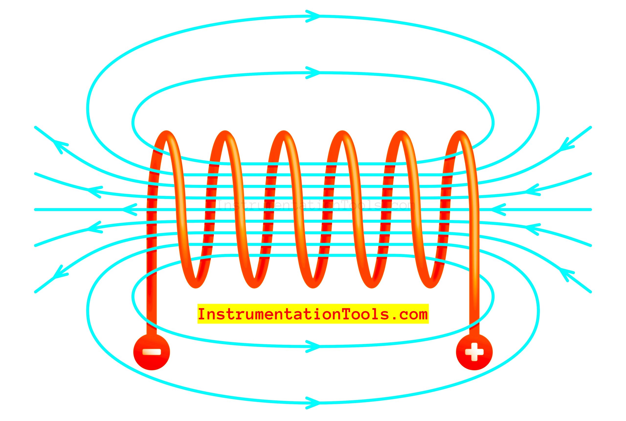
When current flows through a wire, it creates a magnetic field around it. But, in the case of the coil, the magnetic field is concentrated and tends to create hotspots around the coil junctions. These all magnetic fields tend to then create a single large magnetic field around the coil. This magnetic field is so large that it is enough to store the magnetic energy in it.

Now initially, when current starts to flow through the inductor, it provides a very large resistance to it. So, current will not flow through it or will flow in a minimum quantity. The current is flowing as it is and after a period of time, the current will start flowing through it after it has offered the resistance. The time till which it was not allowing current to flow was used by the inductor to store the magnetic field in it.

Inductor Working Principle - Electrical and Electronics Engineering

When the current supply is stopped, then the magnetic field which was stored is released immediately into the electrical field. This will allow current to flow through the line for a period of time even when the power supply has switched off. Once all the magnetic field has been discharged, the current will not flow through the circuit now.

So, the inductors are used to supply the same amount of current every time in a circuit; this means suppose there is a spike, then the inductor will absorb the extra current and when there is under current, then the inductor will release the stored energy in it. It is designed to pass only a certain fixed amount of current. In this way, it helps to control the electric spikes and fluctuations in a circuit.
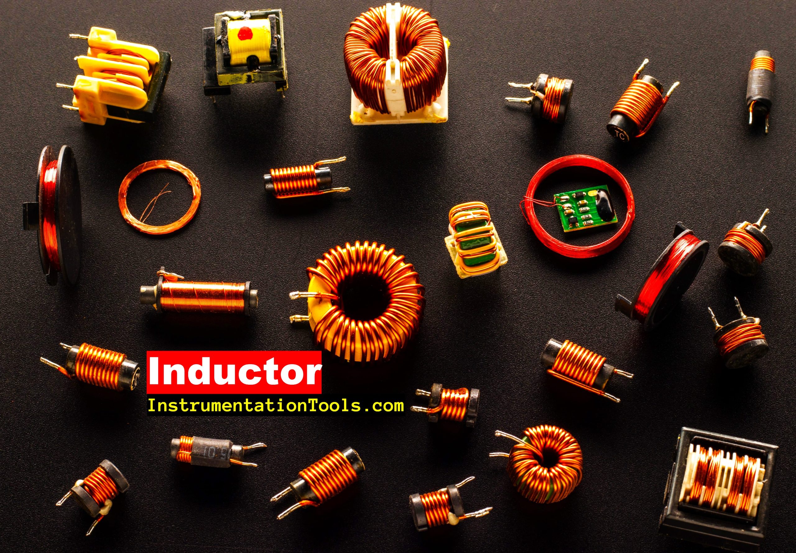
Types of Inductors

The types of inductors depend on the material used for its core coil construction. Let us have a look at the types of inductors used in electrical circuits.

Types of Inductors

Iron core inductor

Iron or ferrite is a ferromagnetic material. One advantage of ferrous materials is that it offers a very high permeability (high magnetic field generation). This increases inductance properties in a great way, but one more major issue is that they suffer from energy losses at higher frequencies.

This is because, ferrous materials have a great amount of skin effect (as frequency increases, the current is unable to dig deeply into the conductor material); resulting in high resistance and losses.

Air core inductor

Air core inductor is the exact opposite of iron core inductors. They use air as the core material; sometimes plastic or ceramic too. They have low permeability and also, they suffer less at higher frequencies. But, due to low permeability, the inductance property is poor at normal frequencies.

Laminated core inductor

As the name implies, a Laminated core inductor is a stack of laminated sheets as the core materials. Basically, when you stack something, the eddy current or energy losses if any tend to decrease because the loop area is small in this case. So, apart from good inductance, they help in minimizing the losses to a great extent.

Toroidal core inductor

The toroidal core inductor is the best type of inductor available for use. It is circular in shape. The circular shape allows for a very large area of magnetic field generation. Due to the abundant magnetic field, the inductance too is very good and also, they have less energy losses.

If you liked this article, then please subscribe to our YouTube Channel for Electrical, Electronics, Instrumentation, PLC, and SCADA video tutorials.

You can also follow us on Facebook and Twitter to receive daily updates.

Read Next:

  • Importance of Neutral Wire
  • Induction Motor Problems
  • Cables between VFD & Motor
  • How to Test a Battery?
  • Electrical & Electronic Devices
Don't Miss Our Updates
Be the first to get exclusive content straight to your email.
We promise not to spam you. You can unsubscribe at any time.
Invalid email address
You've successfully subscribed !

Continue Reading

Motor Protection Circuits
What is Floating Neutral? – Electrical Engineering Basics
Automatic Transfer Switch (ATS) Using Classic Control Circuit
How to Locate Faults in Cables? – Fault Analysis & Location
Contactor – Basics, Wiring, Connection with PLC
Difference Between Short Circuit and Ground Fault
Share This Article
Facebook Whatsapp Whatsapp LinkedIn Copy Link
Share
Leave a Comment

Leave a Reply Cancel reply

Your email address will not be published. Required fields are marked *

Stay Connected

128.3kFollowersLike
69.1kFollowersFollow
210kSubscribersSubscribe
38kFollowersFollow

Categories

Explore More

Difference Between Core and Shell Transformers
What is a Megger? Principle, Advantages, Disadvantages, Applications
Testing a Transistor with a Digital Multimeter
Difference Between Emergency STOP and Emergency Power OFF
How does a Lead Acid Battery Work?
Siemens Standard Drives Application Handbook (PDF)
Types of Earth Leakage Circuit Breaker
Difference Between Circuit Breaker and Fuse

Keep Learning

Electrical Equipment Selection in Hazardous Area

Hazardous Areas in Industry – Electrical Equipment Selection

Purpose of an Electrical Substation

What is a Substation? Purpose of an Electrical Substation

Types of Motor Enclosures

Types of Motor Enclosures

Routine Tests of Transformers

Transformer Testing – Routine Tests of Transformers

Power Outlet

How does Electrical Power Outlet Work?

Difference between Analog Signal and Digital Signal

What are Analog and Digital Signals? Differences, Examples

Difference Between LDR and Photodiode

Difference Between LDR and Photodiode

Electric Motor Winding Temperature Sensors

Electric Motor Winding Temperature Sensors

Learn More

Variable Area Flow Meters

Variable Area Flow Meters – Principle, Advantages, Disadvantages

Circuit Control Devices Multiple Choice Questions

Circuit Control Devices Multiple Choice Questions & Answers

Annunciators - 2

What is a Annunciator ?

Comparison of Flowmeters

Difference between Different Types of Flow Meters

Resistance Temperature Detector (RTD) Questions

Resistance Temperature Detector (RTD) Questions – 1

Closed Tank Level Measurement using DP Transmitter

Closed Tank Level Measurement using DP Transmitters

4-20mA VFD Drive Formula

4-20mA Linear Conversion Calculation for VFD Drive (Formula)

OPC in PLC Systems

OPC in Old PLC Systems

Menu

  • About
  • Privacy Policy
  • Copyright

Quick Links

  • Learn PLC
  • Helping Hand
  • Part Time Job

YouTube Subscribe

Follow US
All rights reserved. Reproduction in whole or in part without written permission is prohibited.
Welcome Back!

Sign in to your account

Username or Email Address
Password

Lost your password?