Inst ToolsInst ToolsInst Tools
  • Ask
  • Courses
  • Videos
  • Q & A
    • Interview
      • Instrumentation
      • Electronics
      • Electrical
      • Practical Questions
    • MCQ
      • Instrumentation MCQ
      • Electrical MCQ
      • Electronics MCQ
      • Control Systems MCQ
      • Analog Electronics MCQ
      • Digital Electronics MCQ
      • Power Electronics MCQ
      • Microprocessor MCQ
      • Multiple Choice Questions
  • EE
    • Electronics
      • Electronics Q & A
      • Electronic Basics
      • Electronic Devices & Circuits
      • Electronics Animation
      • Digital Electronics
    • Electrical
      • Electrical Basics
      • Electrical Q & A
      • Power Electronics
      • Electrical Machines
      • Electrical Animation
      • Power Systems
      • Switchgear & Protection
      • Transmission & Distribution
  • Measure
    • Control Valves
    • Calibration
    • Temperature
    • Pressure
    • Flow
    • Level
    • Analyzers
    • Switches
    • Vibration
    • Solenoid Valve
  • Control
    • PLC Tutorials
    • Control Systems
    • Safety Instrumented System (SIS)
    • Communication
    • Fire & Gas System
  • More
    • Design
    • Tools
    • Animation
    • Basics
    • Formulas
    • Standards
    • TextBooks
    • Common
    • Software
    • Excel Tools
    • Erection & Commissioning
    • Process Fundamentals
    • Videos
    • Books
Search
All rights reserved. Reproduction in whole or in part without written permission is prohibited.
Reading: Well Manometer Principle
Share
Notification Show More
Font ResizerAa
Inst ToolsInst Tools
Font ResizerAa
  • Courses
  • PLC Tutorials
  • Control Systems
Search
  • Ask
  • Courses
  • Videos
  • Q & A
    • Interview
    • MCQ
  • EE
    • Electronics
    • Electrical
  • Measure
    • Control Valves
    • Calibration
    • Temperature
    • Pressure
    • Flow
    • Level
    • Analyzers
    • Switches
    • Vibration
    • Solenoid Valve
  • Control
    • PLC Tutorials
    • Control Systems
    • Safety Instrumented System (SIS)
    • Communication
    • Fire & Gas System
  • More
    • Design
    • Tools
    • Animation
    • Basics
    • Formulas
    • Standards
    • TextBooks
    • Common
    • Software
    • Excel Tools
    • Erection & Commissioning
    • Process Fundamentals
    • Videos
    • Books
Follow US
All rights reserved. Reproduction in whole or in part without written permission is prohibited.
Inst Tools > Blog > Pressure Measurement > Well Manometer Principle

Well Manometer Principle

Last updated: June 21, 2019 4:59 pm
Editorial Staff
Pressure Measurement
1 Comment
Share
2 Min Read
SHARE

Well Manometer Principle

Well Manometer – same as the U-tube except for the reservoir on the high-pressure side. It is sometimes called a single column gauge.

The manometer consists of a metal well of large cross sectional area connected to a glass tube, or limb. This system normally contains mercury as the filling liquid.

As shown in figure above, both the well and the limb are open to atmosphere, in which case the level of mercury in the well is equal to that in the limb.

Well Manometer Principle

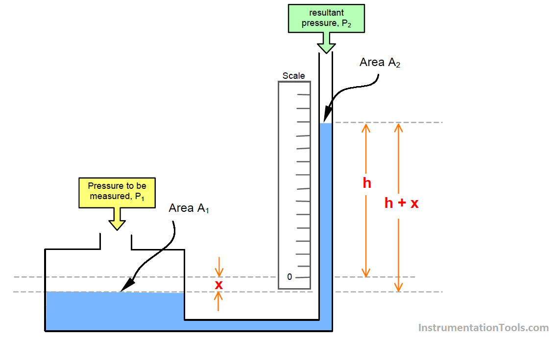
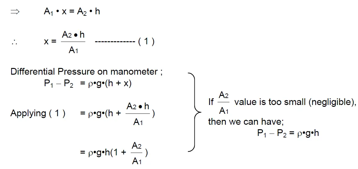
In the well type manometer, the pressure to be measured is normally applied to the well. When pressure applied to the well the level of liquid in the well falls by the distance ” x ” and the level in the limb rises by the distance ” h “.

When the column of liquid (h + x) exerts a pressure equal to the pressure applied to the well, the liquid stops moving.

The value of (h + x) will increase as the pressure to be measured increases and will decrease as the pressure to be measured decreases. The value of (h + x) can be read from a scale positioned as shown in the diagram above.

This scale is normally calibrated in units of pressure, e.g. mm of mercury gauge or Pascal ( Pa ), so that the pressure can be read directly from the device.

Well Manometer Formula

Credits : N Asyiddin

Don't Miss Our Updates
Be the first to get exclusive content straight to your email.
We promise not to spam you. You can unsubscribe at any time.
Invalid email address
You've successfully subscribed !
Pressure Detection Circuit
Inclined-limb Manometer Principle
Diaphragm Pressure Sensors
U-tube Manometer Principle
Absolute Pressure Gauges Principle
Share This Article
Facebook Whatsapp Whatsapp LinkedIn Copy Link
Share
1 Comment
  • Ahmad .Sarhan says:
    April 25, 2020 at 8:31 pm

    how to increase the sensitivity for this one

    Reply

Leave a Reply Cancel reply

Your email address will not be published. Required fields are marked *

Stay Connected

128.3kFollowersLike
69.1kFollowersFollow
208kSubscribersSubscribe
38kFollowersFollow

Categories

Recent Comments

  • Guifty Shimica on Top Non-PLC Certification Courses for Automation Professionals
  • Guifty Shimica on Top Non-PLC Certification Courses for Automation Professionals
  • MIHARITSOA Aina Sitraka on Top Non-PLC Certification Courses for Automation Professionals
  • Vaishnavi on Free Instrumentation Course for Trainee Engineers

Related Articles

Uncertainty Calculations of Pressure Calibration

Uncertainty Calculations of Pressure Calibration

Pressure Gauge Dial

Information on the Pressure Gauge Dial

U tube Manometer Working

Basics of Pressure

Instrumentation Impulse Lines

All About Instrumentation Impulse Lines

Compression load cell Principle

Types of Load Cells

Capacitance Pressure Sensor Works

How Capacitive Pressure Sensor Works ?

Impulse Line Purging and Close Coupling

Impulse Line Purging and Close Coupling of Instruments

Fieldbus Pressure Transmitter Configuration

Foundation Fieldbus Pressure Transmitter Configuration

More Articles

pH Analyzers Questions and Answers

pH Meters Questions & Answers

Electric-driven Air Compressor Troubleshooting

Electric-driven Air Compressor Troubleshooting

Power Supply Sizing for Industrial Automation Systems

Power Supply Sizing for Industrial Automation Systems

Types of Sensors Used in Automobiles

Types of Sensors Used in Automobiles

What is a Condensate Pot? How to Install it?

What is RTD Sensitivity ?

What is RTD Sensitivity ?

How to Remove Control Valve Stem Packing Procedure

The Replacement Procedure for Control Valve Stem Packing

Retrieve from memory card

How to Retrieve PLC Project From Memory Card?

Follow US
All rights reserved. Reproduction in whole or in part without written permission is prohibited.
Welcome Back!

Sign in to your account

Username or Email Address
Password

Lost your password?