This article discusses the PLC program for an automatic water level-based pump control logic using XG-5000 PLC. The system aims to control the process of filling water into a tank automatically. The system will carry out the water filling process based on the water level or when the output valve is open. The system will provide indicators of the ongoing process.
Program Objective
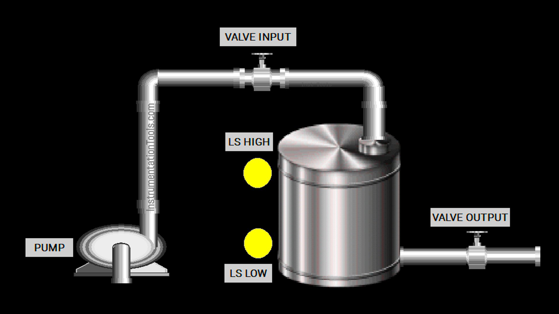
Step-by-Step System:
The system has 2 modes (Level Control Mode and Auto Mode) that can be selected using a Selector Switch.
Level Control Mode:
When the water level is below the minimum limit, the LOW level switch will activate, and the filling process will begin.
When the water level reaches the maximum limit, the HIGH level switch will activate, and the filling process will stop.
Auto Mode:
The filling process will be initiated if the output valve is opened. The output valve can only be operated manually.
Filling Process:
a. The input valve will open.
b. Two seconds later, the water pump will turn on.
Indicators:
a. Filling: The indicator will turn on when the filling process is active.
b. Low Level: The indicator will turn on when the water level in the tank is below the minimum limit.
c. High Level: The indicator will turn on when the water level in the tank reaches the maximum limit.
Water Level-Based Pump Control
IO Mapping
| S.No. | Comment | Input (I) | Output (Q) | Memory Bits | Timers |
|---|---|---|---|---|---|
| 1 | START | P0000 | |||
| 2 | STOP | P0001 | |||
| 3 | MODE | P0002 | |||
| 4 | LS_LOW | P0003 | |||
| 5 | LS_HIGH | P0004 | |||
| 6 | PB_VALVE_OUT | P0005 | |||
| 7 | PUMP | P0040 | |||
| 8 | VALVE_OUT | P0041 | |||
| 9 | VALVE_INPUT | P0042 | |||
| 10 | FILLING | P0043 | |||
| 11 | LOW_LEVEL | P0044 | |||
| 12 | HIGH_LEVEL | P0045 | |||
| 13 | SYSTEM_ON | M0000 | |||
| 14 | IR_PUMP | M0001 | |||
| 15 | TIMER_DELAY1 | T000 |
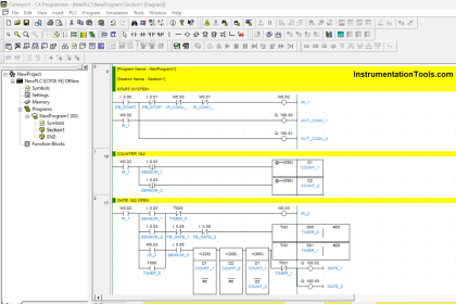
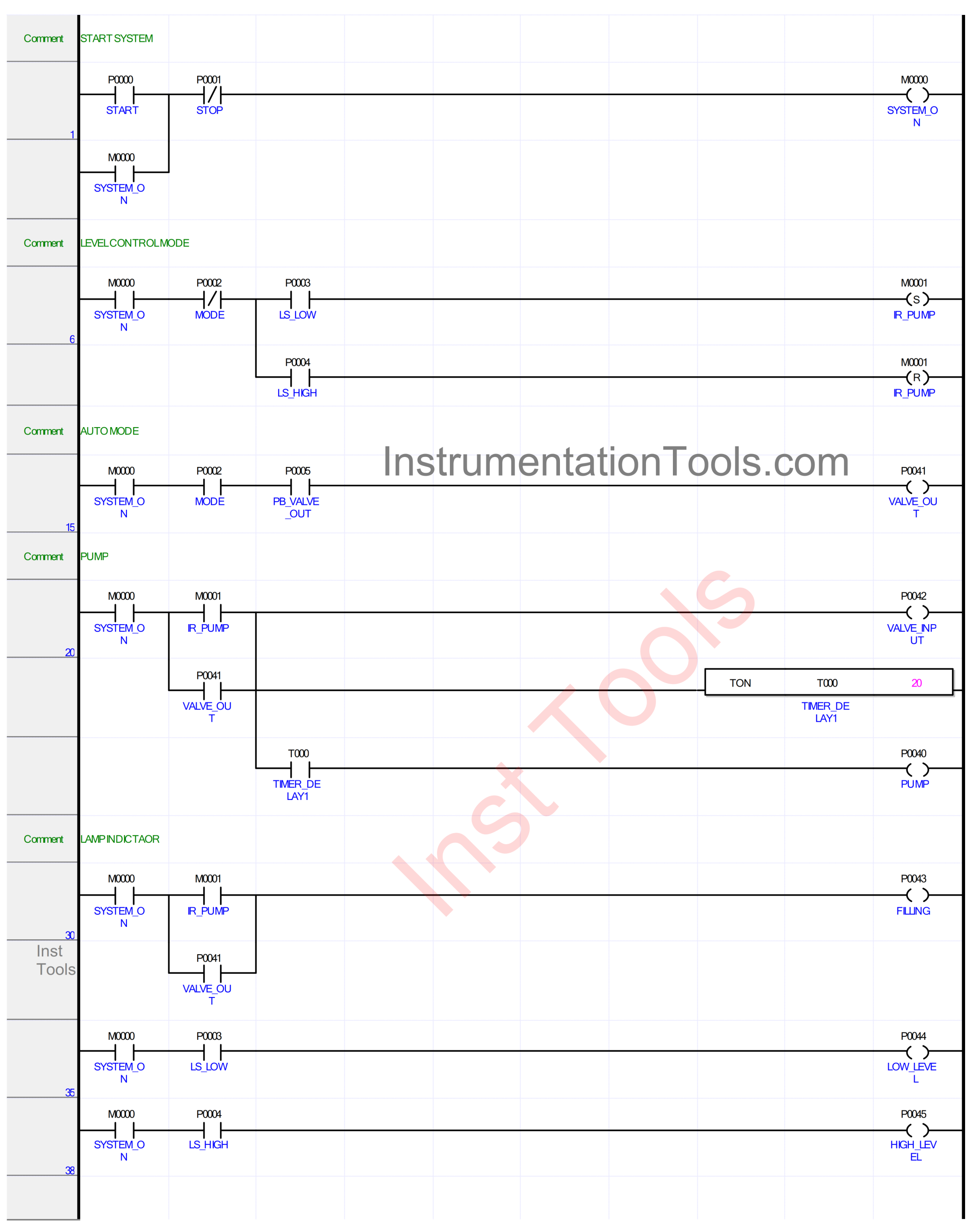
XG-5000 PLC Example
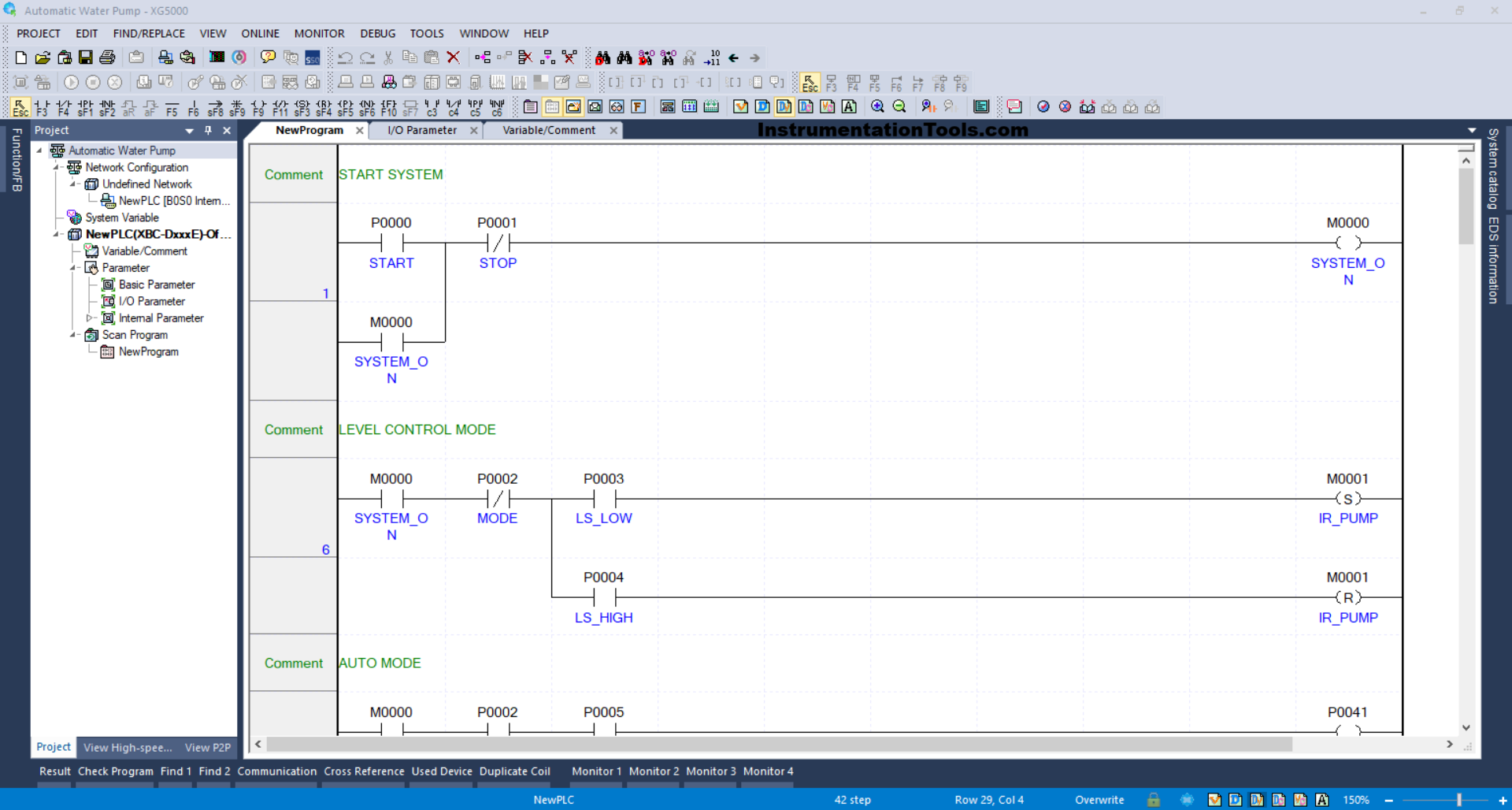
RUNG 1 (START SYSTEM)
In this Rung, when the START (P0000) button is pressed, the memory bit SYSTEM_ON (M0000) will be in the HIGH state. Because it uses Latching, the memory bit SYSTEM_ON (M0000) remains in the HIGH state even though the START (P0000) button has been released.
If the STOP (P0001) button is pressed, the memory bit SYSTEM_ON (M0000) will be in the LOW state.
RUNG 6 (LEVEL CONTROL MODE)
When the NO contact of the memory bit SYSTEM_ON (M0000) and the level switch LS_LOW (P0003) are in the HIGH state, the memory bit IR_PUMP (M0001) will be in the HIGH state.
Because it uses the SET Coil Instruction, the memory bit IR_PUMP (M0001) remains in the HIGH state even though the level switch LS_LOW (P0003) is in the LOW state.
When the NO contact of the level switch LS_HIGH(P0004) is in the HIGH state, the memory bit IR_PUMP (M0001) will be in the LOW state. Because it uses the RESET Coil Instruction.
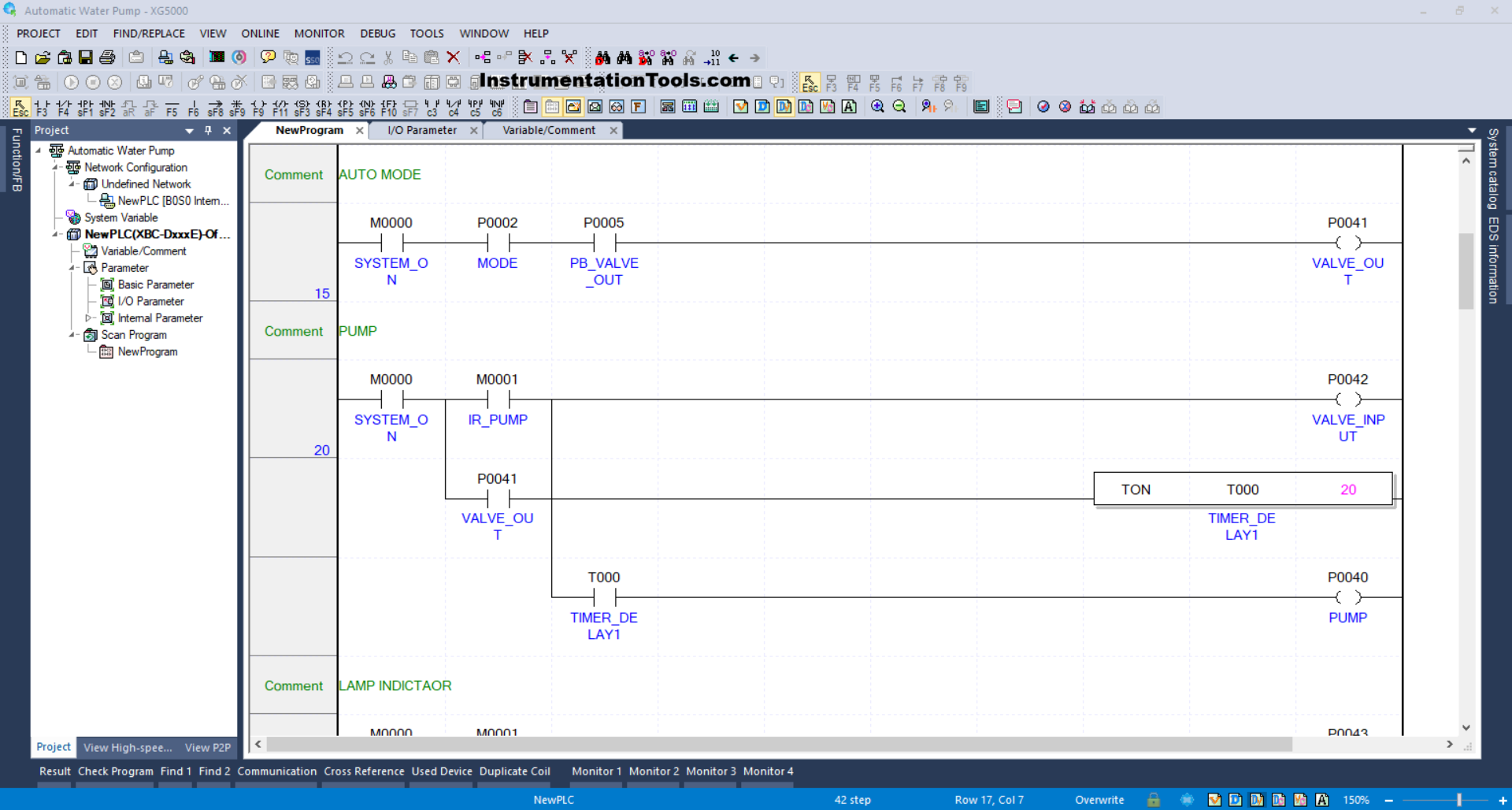
RUNG 15 (AUTO MODE)
When the NO contact of the memory bit SYSTEM_ON (M0000) and the MODE (P0002) selector switch are in the HIGH state and the PB_VALVE_OUT (P0005) button has been pressed, the VALVE_OUT (P0041) output will be OPEN.
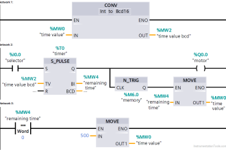
RUNG 20 (PUMP)
In this Rung, when the NO contact of the memory bits SYSTEM_ON (M0000) and IR_PUMP(M0001) are in the HIGH state, the VALVE_INPUT (P0042) output will be OPEN.
The VALVE_INPUT (P0042) output will remain OPEN even though the NO contact of the memory bit IR_PUMP (M0001) is in the LOW state, because it uses Latching.
Next, the TIMER_DELAY1 (T000) timer will start counting up to 2 seconds, and after the timer finishes counting, the PUMP (P0040) output becomes ON.
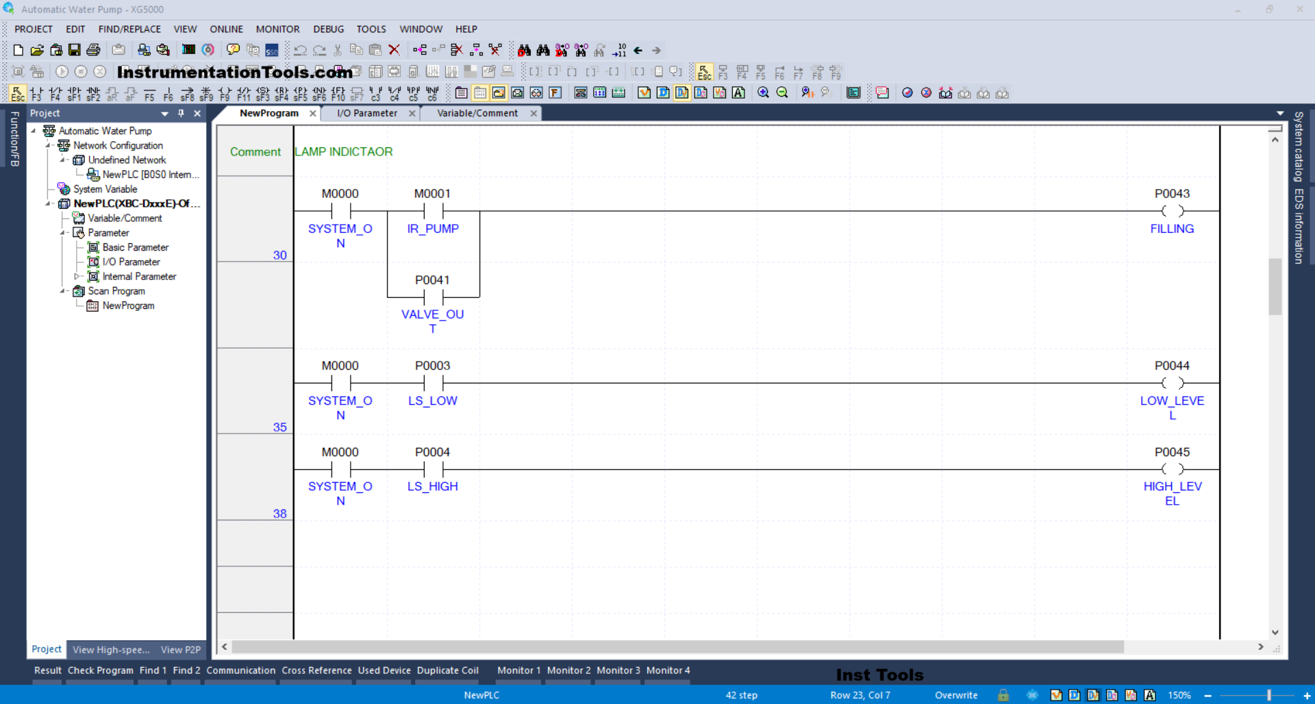
RUNG 30 (LAMP INDICATOR)
In this Rung, when the NO contact of the memory bit SYSTEM_ON (M0000) and IR_PUMP (M0001 are in the HIGH state, the FILLING (P0043) output will be ON.
Or, if the NO contact of the VALVE_OUT (P0041) is in the HIGH state, the FILLING (P0043) output will be ON.
RUNG 35
In this Rung, when the NO contact of the memory bit SYSTEM_ON (M0000) and the level switch LS_LOW (P0003) are in the HIGH state, the LOW_LEVEL (P0044) output will be ON.
RUNG 38
In this Rung, when the NO contact of the memory bit SYSTEM_ON (M0000) and the level switch LS_HIGH (P0004) are in the HIGH state, the HIGH_LEVEL (P0045) output will be ON.
Read Next:
- Siemens HMI Tutorial using UDTs with Faceplates
- How to Create a Faceplate? HMI Visualization?
- PLC Programming Tutorials: User-Defined Data Types
- Difference between Power Cables and Signal Cables
- PLC Program for Sorting & Distribution of Boxes by Height