Inst ToolsInst ToolsInst Tools
  • Courses
  • Automation
    • PLC
    • Control System
    • Safety System
    • Communication
    • Fire & Gas System
  • Instrumentation
    • Design
    • Pressure
    • Temperature
    • Flow
    • Level
    • Vibration
    • Analyzer
    • Control Valve
    • Switch
    • Calibration
    • Erection & Commissioning
  • Interview
    • Instrumentation
    • Electrical
    • Electronics
    • Practical
  • Q&A
    • Instrumentation
    • Control System
    • Electrical
    • Electronics
    • Analog Electronics
    • Digital Electronics
    • Power Electronics
    • Microprocessor
  • Request
Search
  • Books
  • Software
  • Projects
  • Process
  • Tools
  • Basics
  • Formula
  • Power Plant
  • Root Cause Analysis
  • Electrical Basics
  • Animation
  • Standards
  • 4-20 mA Course
  • Siemens PLC Course
Reading: Types of Electrical Wiring
Share
Font ResizerAa
Inst ToolsInst Tools
Font ResizerAa
  • Courses
  • Design
  • PLC
  • Interview
  • Control System
Search
  • Courses
  • Automation
    • PLC
    • Control System
    • Safety System
    • Communication
    • Fire & Gas System
  • Instrumentation
    • Design
    • Pressure
    • Temperature
    • Flow
    • Level
    • Vibration
    • Analyzer
    • Control Valve
    • Switch
    • Calibration
    • Erection & Commissioning
  • Interview
    • Instrumentation
    • Electrical
    • Electronics
    • Practical
  • Q&A
    • Instrumentation
    • Control System
    • Electrical
    • Electronics
    • Analog Electronics
    • Digital Electronics
    • Power Electronics
    • Microprocessor
  • Request
Follow US
All rights reserved. Reproduction in whole or in part without written permission is prohibited.
Inst Tools > Blog > Electrical Basics > Types of Electrical Wiring

Types of Electrical Wiring

There are four types of electrical wiring procedures. They are Cleat wiring, Batten wiring, Casing and caping, and Conduit wiring.

Last updated: September 28, 2022 2:37 pm
R Jagan Mohan Rao
Electrical Basics
No Comments
Share
6 Min Read
SHARE

Basically, there are four types of electrical wiring procedures.

Contents
Cleat WiringAdvantagesDisadvantagesBatten WiringAdvantagesDisadvantagesCasing and CappingAdvantagesDisadvantages Conduit WiringSurface mounting conduit wiring systemConcealed conduit wiringAdvantagesDisadvantages

They are

  • Cleat wiring.
  • Batten wiring.
  • Casing and caping.
  • Conduit wiring.

Cleat Wiring

Cleat Wiring

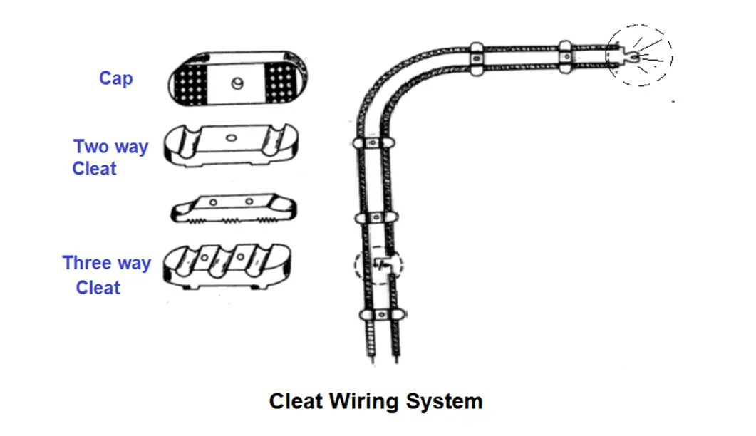
In this type of wiring, the insulated conductors are supported on porcelain or wooden cleat. The cleats have two halves.

One base and another cap. The cables are placed in groves in the base plate and a cap is placed on it.

Cables are held in porcelain or wooden cleats at 6mm above the walls or ceiling.

Cleat wiring is generally used for temporary wiring purposes not as a permanent system of wiring. It is not preferred on domestic premises.

But, it is quite suitable for taking a temporary connection in industrial construction work.

Advantages

  • This fitting is very easy and cheap.
  • This method was very good for temporary fitting where some kind of construction is going on.  

Disadvantages

  • This fitting doesn’t look good.
  • As the cable is kept out, so it has the effect of every kind of environment, a low-quality wire spoils quickly.

Batten Wiring

Batten Wiring

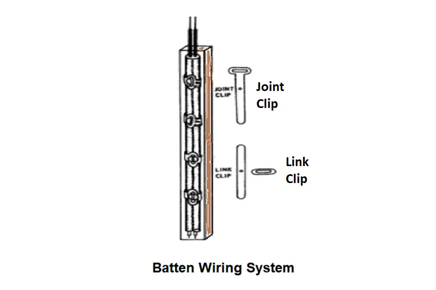
This wiring system is a very old method in which all wires are tied with an iron clip on top of a wooden strip (batten) and this collection is used in large quantities so that the wire is very well sealed with some wooden strip.

This clip is like a belt to a wristwatch. Which is placed on top of the first strip and then by laying wires on top of the strip, it is tied well with this clip.

Advantages

  • Wiring is simple and easy to do
  • This wiring method is cheaper than another wiring.
  • This wiring also looks great.
  • It is also easy to repair this wiring

Disadvantages

  • We can not do this wiring in the open outside the house
  • This wiring is not protected from the external environment because it has a great impact on the weather.
  • The heavy wire cannot be used in this wiring
  • This wiring is up to 220 V only.
  • Require more cables and wires.
  • Cable sag may take place after a long period.

Casing and Capping

Casing and Caping Wiring System

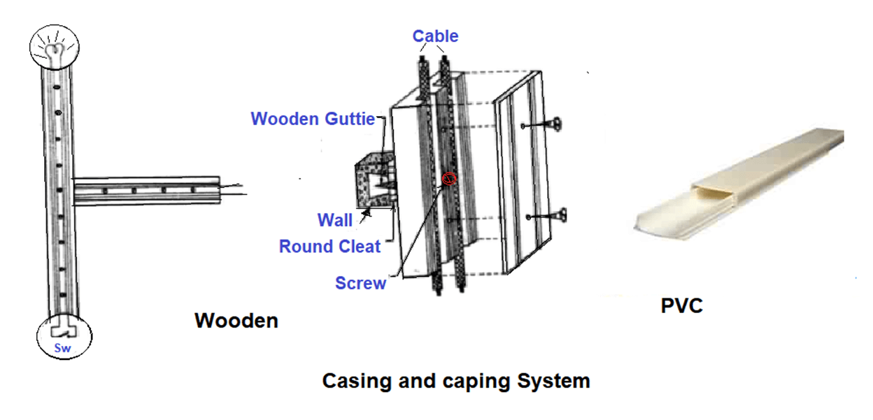
This type of wiring is very popular. Because this wiring system is very easy to do and it is also very cheap.

If it is done above the walls, then anyone can fit it very easily in this wiring fitting, the wires are placed inside the plastic casing or wooden enclosures.

It is a kind of open fitting it is covered from the top so that it looks good and looks more secure.

Advantages

  • This wiring system is much easier and cheaper than other wiring systems.
  • This wiring system is very strong and long-lasting.
  • One can make changes to this wiring very easily.
  • There is no risk of electric shock as it covers the wires well.
  • If phase and neutral follow a different path, repair becomes easy.

Disadvantages 

  • if there is a fire in the wires inside it, then this whole fitting can burn. 

Conduit Wiring

The conduit wiring system is of two types.

  1. Surface mounting.
  2. Concealed conduit wiring.

Surface mounting conduit wiring system

Surface mounting conduit wiring system

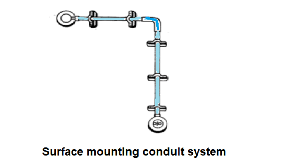
Conduits carrying the PVC insulated wires can be installed on the surface of the walls or concealed in the walls and the ceiling.

Concealed conduit wiring

Conduit wiring is a system, basically, wires or cables which are routed in metal or plastic inside the wall.

Conduits isolate wires to avoid exposure, thereby reducing the risk of fires, short circuits, fire, electrocution.

Modern practice is the hidden installation of the conduit in the plaster of the wall, so that appearance of the house or the building remains unaffected. Conduits are available in standard lengths.

The conduits system for each circuit must be erected completely before any cable is drawn in.

Advantages

  • A conduit wiring system is best for domestic and commercial installations.
  • It provides proper protection to the installation against shock, fire hazards mechanical damage. 
  • Protected from external damage due to rodents, short circuit.
  • Conduit is durable and strong, can last for a long time.
  • Great protection as it is more robust.

Disadvantages

  • If cable got damaged. replacement of cable is difficult compared to any other.
  • Requires skill in running the conduit and wires through it.
  • The cost, time, and efforts of installation are high.

Reference: Engineering Basics: Electrical, Electronics, and Computer Engineering by T.Thyagarajan

Read Next:

  • vacuum circuit breaker
  • Single versus Three-phase Power
  • Motor Protection Circuit
  • Stepper Motor Principle
Don't Miss Our Updates
Be the first to get exclusive content straight to your email.
We promise not to spam you. You can unsubscribe at any time.
Invalid email address
You've successfully subscribed !

Continue Reading

What is Electrical Busbar? Types, Advantages, Disadvantages
Why is HV Testing important in Electrical Panels?
Download Electrical Enclosure Book
Control Two Motors in Sequence after Time Delay – Circuit, Operation
What is a Substation? Purpose of an Electrical Substation
Dynamic Braking Resistor in VFD
Share This Article
Facebook Whatsapp Whatsapp LinkedIn Copy Link
Share
Leave a Comment

Leave a Reply Cancel reply

Your email address will not be published. Required fields are marked *

Stay Connected

128.3kFollowersLike
69.1kFollowersFollow
210kSubscribersSubscribe
38kFollowersFollow

Categories

Explore More

How to Connect a 3 Phase Motor in Star and Delta Connections?
Difference Between RCCB and MCCB
What is a Solid State Relay? – Working Principle, Types of Control
Motor Classic Control Circuits using Single Push button
Electric Motor Winding Temperature Sensors
What is a VFD? – Theory, Advantages, Disadvantages
Difference Between AIS and GIS Panels
What is Electrical Panel Door Earth Bonding? Explained

Keep Learning

What is a Bus Coupler in Electrical Panel

What is a Bus Coupler in Electrical Panel?

Bus Riser in Switchgear

Bus Riser in Switchgear

VFD Braking

DC Injection Braking in VFD

Difference Between Contactor and Relay

Difference Between Contactor and Relay

Why is Motor Control Required in Control Systems

Why is Motor Control Required in Control Systems?

Electrical Power Grid Automation

Electrical Power Grid Automation

Typical Switchyard Layout

Electrical Substation – Busbar Arrangements and Layouts

Floating Neutral - Electrical Engineering Basics

What is Floating Neutral? – Electrical Engineering Basics

Learn More

Why 4-20mA Standard is so popular

Why 4-20 mA Standard is so popular ?

Difference Between Skin Effect and Proximity Effect

Difference Between Skin Effect and Proximity Effect

Analog Electronics Objective Questions

Analog Electronics Objective Questions – Set 3

Transmission Lines Protection Questions Answers

Transmission Lines Protection Questions Answers

Electrical Traction Multiple Choice Questions and Answers

Electrical Traction Multiple Choice Questions and Answers

PLC Ladder Logic for Motor Control

PLC Program for Motor Starter

Online Simulation

Relay Permissive and interlock circuits

Basics of Permissive and Interlock Circuits

Menu

  • About
  • Privacy Policy
  • Copyright

Quick Links

  • Learn PLC
  • Helping Hand
  • Part Time Job

YouTube Subscribe

Follow US
All rights reserved. Reproduction in whole or in part without written permission is prohibited.
Welcome Back!

Sign in to your account

Username or Email Address
Password

Lost your password?