The purpose of proof testing is to detect the failures within the transmitter that are not detected by the regular diagnostics of the transmitter. Of main concern are undetected failures that prevent the safety instrumented function from performing its intended function.
The frequency of the proof tests (or the proof test interval) is to be determined in the reliability calculations for the safety instrumented functions for which the transmitter is applied. The actual proof tests must be performed more frequently or as frequently as specified in the calculation in order to maintain the required safety integrity of the safety instrumented function.
The following tests need to be specifically executed when a proof test is performed. The results of the proof test need to be documented and this documentation should be part of a plant safety management system. Failures that are detected should be reported to the manufacturer.
The personnel performing the proof test of the transmitter should be trained in SIS operations including bypass procedures, transmitter maintenance, and company management of change procedures.
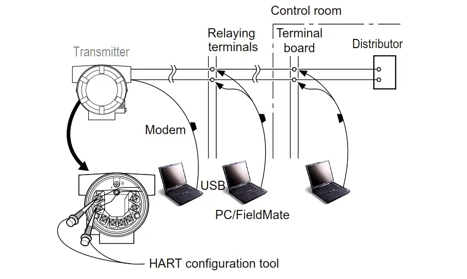
Tools required: Handheld terminal (HART)
1. Bypass the safety PLC or take other appropriate action to avoid a false trip.
2. Send a HART command to the transmitter to go to the high alarm current output and verify that the analog current reaches that value.
3. Send a HART command to the transmitter to go to the low alarm current output and verify that the analog current reaches that value.
4. Use the HART communicator to view detailed device status to ensure no alarms or warnings are present in the transmitter.
5. Perform reasonability check on the sensor value(s) versus an independent estimate (i.e. from direct monitoring of BPCS value) to show current reading is good.
6. Restore the loop to full operation.
7. Remove the bypass from the safety PLC or otherwise restore normal operation.
Remarks The output needs to be monitored to assure that the transmitter communicates the correct signal.
Source: Yokogawa
PLC ladder logic design to control 3 motors with toggle switch and explain the program…
VFD simulator download: Master the online tool from the Yaskawa V1000 & programming software for…
The conveyor sorting machine is widely used in the packing industries using the PLC program…
Learn the example of flip-flop PLC program for lamps application using the ladder logic to…
In this article, you will learn the STAR DELTA programming using PLC controller to start…
Lube oil consoles of rotary equipment packages in industrial process plants are usually equipped with…
