Inst ToolsInst ToolsInst Tools
  • Courses
  • Automation
    • PLC
    • Control System
    • Safety System
    • Communication
    • Fire & Gas System
  • Instrumentation
    • Design
    • Pressure
    • Temperature
    • Flow
    • Level
    • Vibration
    • Analyzer
    • Control Valve
    • Switch
    • Calibration
    • Erection & Commissioning
  • Interview
    • Instrumentation
    • Electrical
    • Electronics
    • Practical
  • Q&A
    • Instrumentation
    • Control System
    • Electrical
    • Electronics
    • Analog Electronics
    • Digital Electronics
    • Power Electronics
    • Microprocessor
  • Request
Search
  • Books
  • Software
  • Projects
  • Process
  • Tools
  • Basics
  • Formula
  • Power Plant
  • Root Cause Analysis
  • Electrical Basics
  • Animation
  • Standards
  • 4-20 mA Course
  • Siemens PLC Course
Reading: Transmitter Calibration Procedure
Share
Font ResizerAa
Inst ToolsInst Tools
Font ResizerAa
  • Courses
  • Design
  • PLC
  • Interview
  • Control System
Search
  • Courses
  • Automation
    • PLC
    • Control System
    • Safety System
    • Communication
    • Fire & Gas System
  • Instrumentation
    • Design
    • Pressure
    • Temperature
    • Flow
    • Level
    • Vibration
    • Analyzer
    • Control Valve
    • Switch
    • Calibration
    • Erection & Commissioning
  • Interview
    • Instrumentation
    • Electrical
    • Electronics
    • Practical
  • Q&A
    • Instrumentation
    • Control System
    • Electrical
    • Electronics
    • Analog Electronics
    • Digital Electronics
    • Power Electronics
    • Microprocessor
  • Request
Follow US
All rights reserved. Reproduction in whole or in part without written permission is prohibited.
Inst Tools > Blog > Calibration > Transmitter Calibration Procedure

Transmitter Calibration Procedure

Last updated: January 26, 2020 11:22 pm
Editorial Staff
Calibration
6 Comments
Share
5 Min Read
SHARE

In today’s environment of shrinking cost margins and increased regulations, maintaining properly calibrated equipment becomes ever important. Even the smallest inaccuracy in process measurements can cause a significant loss in revenue, especially if the process handles large volumes.

Contents
Instrument LoopsSmart TransmittersCalibration GuidelinesGravitational Constants and CorrectionsGeneral Calibration Routine

Electronic equipment can lose accuracy over a period of time, leading to incorrect readings; this is where calibration comes in. Calibrating electronic equipment, in this case transmitters, brings the measured values of the device in line with a known value from an applied standard.

Instrument Loops

In order to understand transmitter calibration, it may be beneficial to first review instrument loops. An instrument loop refers to a configuration of equipment, connected in such a way to deliver power to all devices and obtain a reading from these devices.  An instrument loop can be either electrical or pneumatic.

The figure below shows a simple instrument loop with a power supply, transmitter, and a meter to measure current in the loop.

Transmitter Calibration

Smart Transmitters

Smart transmitters are microprocessor-based transmitters that are capable of being reprogrammed with various parameters without the need for board replacement.

Smart transmitters are more accurate than traditional analog transmitters, have a much greater turndown ratio, and are much easier to calibrate.

Calibration Guidelines

All calibrations should follow some general guidelines, which are true of any type of transmitter, smart or traditional. Some of the guidelines are discussed here.

Primary vs. Secondary standards

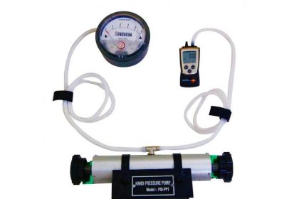
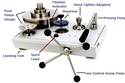
  • Primary standards produce a certified output that can be used to calibrate a piece of equipment. Deadweight testers are examples of primary standards. These devices use a precision mass to measure pressure.
  • Secondary standards typically measure a variable with a transducer or electronics, then display it electronically.

Gravitational Constants and Corrections

Since the gravitational constant throughout the world changes slightly from place to place, this must be taken into account when using a primary or mass-to-pressure device like a dead weight tester.

When using a primary tester to calibrate an instrument, make sure that the weights have the proper gravitational constant stamped on them for the area the tester is being used in.

Some commonly used constants are below:

  • “Standard/International” gravity is 980.665 cm/sec2
  • US mean gravity is 980.000 cm/sec2

All instrument calibrations should be made to .1% of calibrated span.

General Calibration Routine

All calibrations have common elements.  The following is a general procedure for performing any calibration:

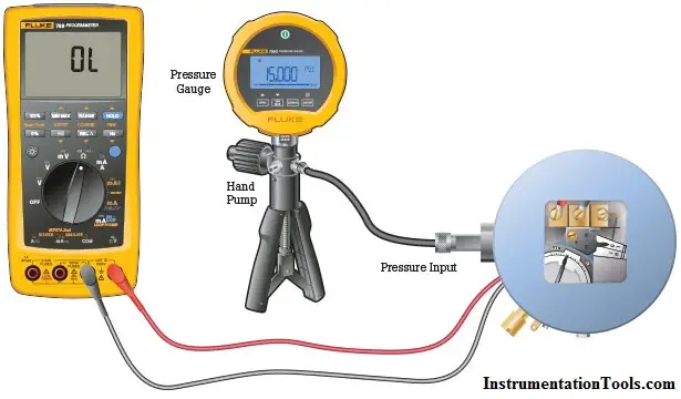
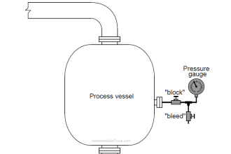
  1. Isolate the transmitter from the source. This means taking the transmitter off service.
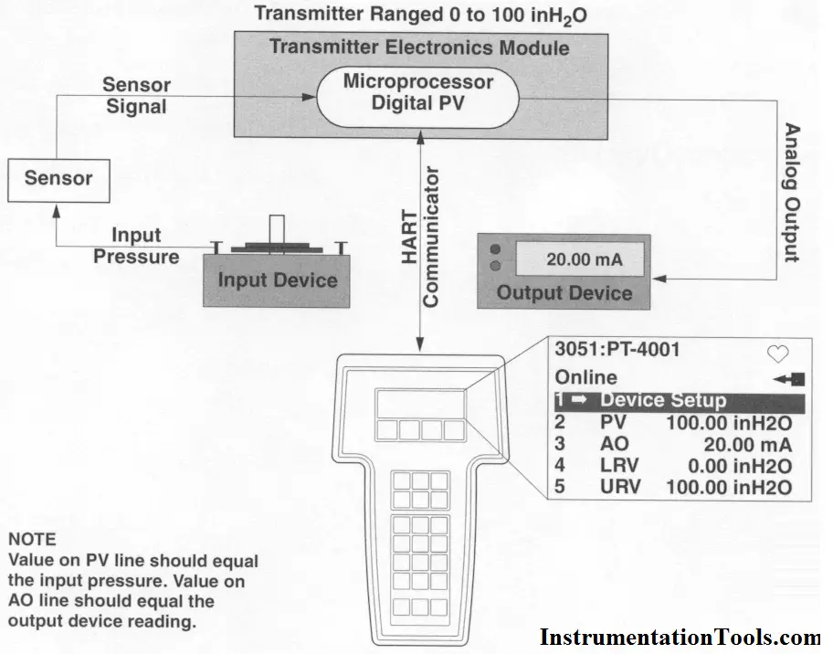
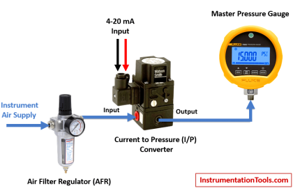
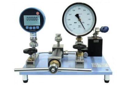
  2. Connect a primary device, such as a dead weight tester or a decade box, to the input of the transmitter.  Make sure the primary device has been certified.  The setup should be similar to the figure below.  In this figure, a HART communicator has also been connected to aid in programming a smart transmitter.
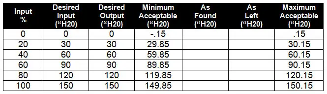
  3. Record on the appropriate form.  A sample chart is shown below for a 0 to 150“ differential pressure transmitter.
  4. Apply the desired input from the table to the transmitter and read the output.  Record it in the chart under the “As Found” column.
  5. If the “As Found” number is outside of the minimum acceptable and the maximum acceptable ranges, then the transmitter must be recalibrated. Even if the readings are inside the limits, but still a bit off, it is a good idea to recalibrate the transmitter.
  6. Recalibrate the transmitter according to the procedure for that transmitter.  This usually involves putting the 0% value of input on the transmitter and zeroing the transmitter to 4 milliamps out. Then, put the 100% value on the transmitter and set the span to read 20 milliamps.
  7. Perform the calibration checks again as in step 4 and record the values in the “As Left” column.

Transmitter Calibration

Transmitter Calibration Report

 Also Read: How are HART Instruments Calibrated

Don't Miss Our Updates
Be the first to get exclusive content straight to your email.
We promise not to spam you. You can unsubscribe at any time.
Invalid email address
You've successfully subscribed !

Continue Reading

Pressure Gauge Functional Testing
Pressure Safety Valve Leak Test Procedure (PSV Testing)
Pressure Transmitter Calibration Procedure
Differential Pressure Sensors Calibration Procedure
Ultrasonic Level Transmitter Principle, Limitations, Calibration and configuration
How to Calibrate Load Cells in Weighing Applications?
Share This Article
Facebook Whatsapp Whatsapp LinkedIn Copy Link
Share
6 Comments
  • D.k,mish4a says:
    February 26, 2016 at 3:41 pm

    I want to required instruments calibration tools

    Reply
  • Baiju says:
    February 28, 2016 at 9:22 am

    This website is so helpful however i need to know more about panel(Encloser) design and wiring(that means power supply to transformer to relays to controllers and vfd from there to field instruments and feedbacks like this…i need to know it clearly how it design and wire it

    Reply
  • md danish says:
    March 3, 2016 at 2:42 pm

    Plz make a pdf book for calibiration for us …plzz with help we can download a pdf book by ur site..

    Reply
  • Tushar says:
    May 18, 2016 at 6:55 am

    Thank you ,

    Reply
  • Magnus says:
    June 1, 2016 at 9:10 am

    Please would appreciate a detailed write-up on panel design and wiring.

    Reply
  • Rakesh says:
    August 7, 2016 at 6:28 am

    This website is very usefull for all instrumentation people.But sir please help us to get this things downloaded or saved in our devices.it would be really helpfull.

    Reply

Leave a Reply Cancel reply

Your email address will not be published. Required fields are marked *

Stay Connected

128.3kFollowersLike
69.1kFollowersFollow
210kSubscribersSubscribe
38kFollowersFollow

Categories

Explore More

Step by Step Guide for Gas Flow Meter Calibration
Calibration of Measuring Instruments – Significance, Costs & Risks
Open Tank DP Level Transmitter Calibration
Instrument Turndown Ratio
Displacer (buoyancy) Level Transmitter Principle, Limitations, Design, Installation & Calibration
As-found and As-left Documentation during Calibration
Pressure Gauge Calibration according to Standard DKD-R-6-1
DeadWeight Tester Questions

Keep Learning

Single Position Calibration of Temperature Bath

Single Position Calibration of Temperature Bath

what is calibration

Important Terms in Calibration

Closed tank DP Level Transmitter with wet leg elevation zero remote mount Calibration

Closed tank DP Level Transmitter with wet leg elevation zero remote mount Calibration

DP Diaphragm Capillary Seal Level instrument

DP Diaphragm Capillary Seal Level instrument Calibration Procedure

Smart Transmitter Calibration Tutorial

Smart Transmitter Calibration Tutorial Part 1

Multimeter Digits

Multimeter – What Do Digits and Counts Mean?

Selection of Master Instrument for Calibration

Selection of Master Instrument for Calibration

Closed-tank-DP-Level-Transmitter-with-wet-leg-Zero-elevation-Calibration

Closed tank DP Level Transmitter with wet leg Zero elevation Calibration

Learn More

Pressure Gauges with Zero Adjustment

Pressure Gauges Zero Adjustment

HMI book

HMI Handbook

Nuclear Level Measurement

Nuclear Level Detectors Cascade or Master/Slave concept

PLC to PLC Communication using S7 Connection

PLC to PLC Communication using S7 Connection PUT & GET Instructions

ON OFF Control Principle

On/off Control Theory

Free WinCC SCADA Training Course

Free SCADA Training Course

Seebeck Effect

Seebeck Effect Theory

PLC Scan Time

PLC Scan Time

Menu

  • About
  • Privacy Policy
  • Copyright

Quick Links

  • Learn PLC
  • Helping Hand
  • Part Time Job

YouTube Subscribe

Follow US
All rights reserved. Reproduction in whole or in part without written permission is prohibited.
Welcome Back!

Sign in to your account

Username or Email Address
Password

Lost your password?