A linear amplifier provides amplification of a signal without any distortion so that the output signal is an exact amplified replica of the input signal. A voltage-divider biased transistor with a sinusoidal ac source capacitively coupled to the base through C1 and a load capacitively coupled to the collector through C2 is shown in Figure. The coupling capacitors block DC and thus prevent the internal source resistance, Rs, and the load resistance, RL, from changing the dc bias voltages at the base and collector.
The capacitors ideally appear as shorts to the signal voltage. The sinusoidal source voltage causes the base voltage to vary sinusoidally above and below its dc bias level, VBQ. The resulting variation in base current produces a larger variation in collector current because of the current gain of the transistor.
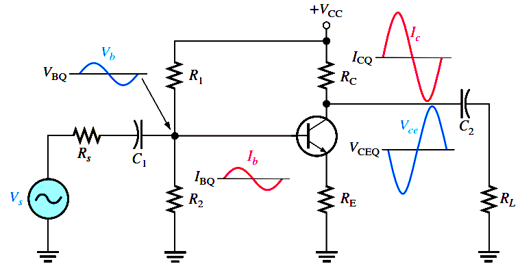
As the sinusoidal collector current increases, the collector voltage decreases. The collector current varies above and below its Q-point value, ICQ, in phase with the base current. The sinusoidal collector-to-emitter voltage varies above and below its Q-point value, VCEQ, 180° out of phase with the base voltage, as illustrated in Figure. A transistor always produces a phase inversion between the base voltage and the collector voltage.
A Graphical Picture
The operation just described can be illustrated graphically on the ac load line, as shown in Below Figure. The sinusoidal voltage at the base produces a base current that varies above and below the Q-point on the ac load line, as shown by the arrows.
Fig : Graphical ac load line operation of the amplifier showing the variation of the base current, collector current, and collector-to-emitter voltage about their dc Q-point values. Ib and Ic are on different scales.
Lines projected from the peaks of the base current, across to the IC axis, and down to the VCE axis, indicate the peak-to-peak variations of the collector current and collector-to- emitter voltage, as shown. The ac load line differs from the dc load line because the effective ac collector resistance is RL in parallel with RC and is less than the dc collector resistance RC alone.
Learn the example of flip-flop PLC program for lamps application using the ladder logic to…
In this article, you will learn the STAR DELTA programming using PLC controller to start…
Lube oil consoles of rotary equipment packages in industrial process plants are usually equipped with…
Rotating equipment packages such as pumps, compressors, turbines need the lube oil consoles for their…
This article explains how to blink lights in ladder logic with a detailed explanation video…
In this article, a simple example will teach you the conversion from Boolean algebra to…

