What is a Zener Diode?
A Zener diode is a special type of rectifying diode that can handle breakdown due to reverse breakdown voltage without failing completely.
Here we will discuss the concept of using diodes to regulate voltage drop and how the Zener diode operates in reverse-bias mode to regulate voltage in a circuit.
How does Diode Regulate Voltage drop?
If we connect a diode and resistor in series with a DC voltage source so that the diode is forward-biased, the voltage drop across the diode will remain fairly constant over a wide range of power supply voltages as in Figure below (a).
According to the “diode equation” here, the current through a forward-biased PN junction is proportional to e raised to the power of the forward voltage drop. Because this is an exponential function, current rises quite rapidly for modest increases in voltage drop.
Another way of considering this is to say that voltage dropped across a forward-biased diode changes little for large variations in diode current. In the circuit shown in Figure below (a), diode current is limited by the voltage of the power supply, the series resistor, and the diode\’s voltage drop, which as we know doesn\’t vary much from 0.7 volts.
If the power supply voltage were to be increased, the resistor\’s voltage drop would increase almost the same amount, and the diode\’s voltage drop just a little.
Conversely, a decrease in power supply voltage would result in an almost equal decrease in resistor voltage drop, with just a little decrease in diode voltage drop. In a word, we could summarize this behavior by saying that the diode is regulating the voltage drop at approximately 0.7 volts.
Voltage Regulation
Voltage regulation is a useful diode property to exploit. Suppose we were building some kind of circuit which could not tolerate variations in power supply voltage, but needed to be powered by a chemical battery, whose voltage changes over its lifetime. We could form a circuit as shown and connect the circuit requiring steady voltage across the diode, where it would receive an unchanging 0.7 volts.
This would certainly work, but most practical circuits of any kind require a power supply voltage in excess of 0.7 volts to properly function.
One way we could increase our voltage regulation point would be to connect multiple diodes in series, so that their individual forward voltage drops of 0.7 volts each would add to create a larger total.
For instance, if we had ten diodes in series, the regulated voltage would be ten times 0.7, or 7 volts in Figure below (b).

Forward biased Si reference: (a) single diode, 0.7V, (b) 10-diodes in series 7.0V.
So long as the battery voltage never sagged below 7 volts, there would always be about 7 volts dropped across the ten-diode “stack.”
How Zener Diodes Regulate Voltage?
If larger regulated voltages are required, we could either use more diodes in series (an inelegant option, in my opinion), or try a fundamentally different approach.
We know that diode forward voltage is a fairly constant figure under a wide range of conditions, but so is reverse breakdown voltage, and breakdown voltage is typically much, much greater than forward voltage.
If we reversed the polarity of the diode in our single-diode regulator circuit and increased the power supply voltage to the point where the diode “broke down” (could no longer withstand the reverse-bias voltage impressed across it), the diode would similarly regulate the voltage at that breakdown point, not allowing it to increase further as in Figure below (a).

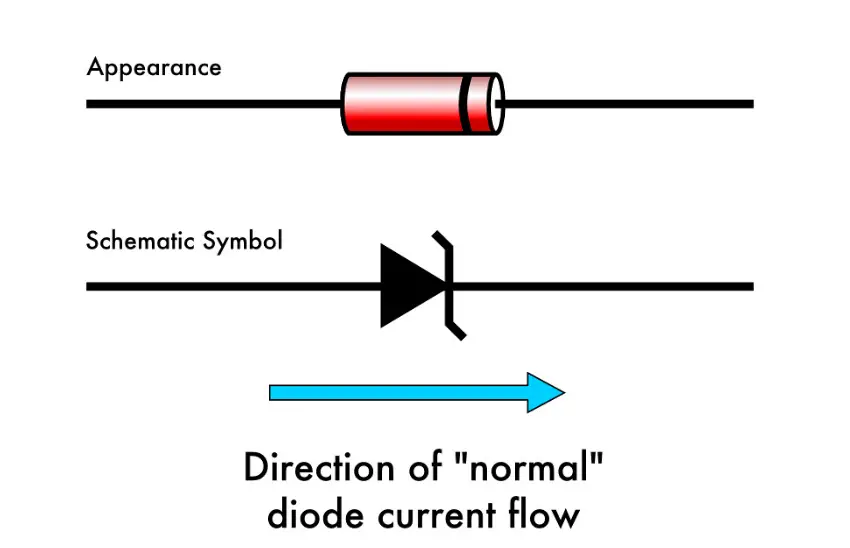
(a) Reverse biased Si small-signal diode breaks down at about 100V. (b) Symbol for Zener diode.
Unfortunately, when normal rectifying diodes “break down,” they usually do so destructively. However, it is possible to build a special type of diode that can handle breakdown without failing completely. This type of diode is called a zener diode, and its symbol looks like Figure above (b).
When forward-biased, zener diodes behave much the same as standard rectifying diodes: they have a forward voltage drop which follows the “diode equation” and is about 0.7 volts.
In reverse-bias mode, they do not conduct until the applied voltage reaches or exceeds the so-called zener voltage, at which point the diode is able to conduct substantial current, and in doing so will try to limit the voltage dropped across it to that zener voltage point.
So long as the power dissipated by this reverse current does not exceed the diode\’s thermal limits, the diode will not be harmed.
Zener Diode Circuit
Zener diodes are manufactured with zener voltages ranging anywhere from a few volts to hundreds of volts.
This zener voltage changes slightly with temperature, and like common carbon-composition resistor values, may be anywhere from 5 percent to 10 percent in error from the manufacturer\’s specifications.
However, this stability and accuracy is generally good enough for the zener diode to be used as a voltage regulator device in common power supply circuit in Figure below.

Zener diode regulator circuit, Zener voltage = 12.6V).
Please take note of the zener diode\’s orientation in the above circuit: the diode is reverse-biased, and intentionally so. If we had oriented the diode in the “normal” way, so as to be forward-biased, it would only drop 0.7 volts, just like a regular rectifying diode.
If we want to exploit this diode\’s reverse breakdown properties, we must operate it in its reverse-bias mode. So long as the power supply voltage remains above the zener voltage (12.6 volts, in this example), the voltage dropped across the zener diode will remain at approximately 12.6 volts.
Like any semiconductor device, the zener diode is sensitive to temperature. Excessive temperature will destroy a zener diode, and because it both drops voltage and conducts current, it produces its own heat in accordance with Joule\’s Law (P=IE).
Therefore, one must be careful to design the regulator circuit in such a way that the diode\’s power dissipation rating is not exceeded. Interestingly enough, when zener diodes fail due to excessive power dissipation, they usually fail shorted rather than open.
A diode failed in this manner is readily detected: it drops almost zero voltage when biased either way, like a piece of wire.
Analysis of Zener Diode Regulating Circuit
Let\’s examine a zener diode regulating circuit mathematically, determining all voltages, currents, and power dissipations.
Taking the same form of circuit shown earlier, we\’ll perform calculations assuming a zener voltage of 12.6 volts, a power supply voltage of 45 volts, and a series resistor value of 1000 Ω (we\’ll regard the zener voltage to be exactly 12.6 volts so as to avoid having to qualify all figures as “approximate” in Figure below (a)
If the zener diode\’s voltage is 12.6 volts and the power supply\’s voltage is 45 volts, there will be 32.4 volts dropped across the resistor (45 volts – 12.6 volts = 32.4 volts). 32.4 volts dropped across 1000 Ω gives 32.4 mA of current in the circuit. (Figure below (b))

(a) Zener Voltage regulator with 1000 Ω resistor. (b) Calculation of voltage drops and current.
Power is calculated by multiplying current by voltage (P=IE), so we can calculate power dissipations for both the resistor and the zener diode quite easily:
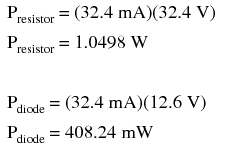
A zener diode with a power rating of 0.5 watt would be adequate, as would a resistor rated for 1.5 or 2 watts of dissipation.
Zener Diode Circuit with Higher Resistances
If excessive power dissipation is detrimental, then why not design the circuit for the least amount of dissipation possible? Why not just size the resistor for a very high value of resistance, thus severely limiting current and keeping power dissipation figures very low?
Take this circuit, for example, with a 100 kΩ resistor instead of a 1 kΩ resistor. Note that both the power supply voltage and the diode\’s zener voltage in Figure below are identical to the last example:

Zener regulator with 100 kΩ resistor.
With only 1/100 of the current we had before (324 µA instead of 32.4 mA), both power dissipation figures should be 100 times smaller:

Considerations with Load Resistance
Seems ideal, doesn\’t it? Less power dissipation means lower operating temperatures for both the diode and the resistor, and also less wasted energy in the system, right?
A higher resistance value does reduce power dissipation levels in the circuit, but it unfortunately introduces another problem. Remember that the purpose of a regulator circuit is to provide a stable voltage for another circuit.
In other words, we\’re eventually going to power something with 12.6 volts, and this something will have a current draw of its own.
Lower value Dropping Resistor Consideration
Consider our first regulator circuit, this time with a 500 Ω load connected in parallel with the zener diode in Figure below.

Zener regulator with 1000 Ω series resistor and 500 Ω load.
If 12.6 volts is maintained across a 500 Ω load, the load will draw 25.2 mA of current. In order for the 1 kΩ series “dropping” resistor to drop 32.4 volts (reducing the power supply\’s voltage of 45 volts down to 12.6 across the zener), it still must conduct 32.4 mA of current. This leaves 7.2 mA of current through the zener diode.
Now consider our “power-saving” regulator circuit with the 100 kΩ dropping resistor, delivering power to the same 500 Ω load. What it is supposed to do is maintain 12.6 volts across the load, just like the last circuit. However, as we will see, it cannot accomplish this task. (Figure below)

Zener non-regulator with 100 KΩ series resistor with 500 Ω load.>
With the larger value of dropping resistor in place, there will only be about 224 mV of voltage across the 500 Ω load, far less than the expected value of 12.6 volts! Why is this? If we actually had 12.6 volts across the load, it would draw 25.2 mA of current, as before.
This load current would have to go through the series dropping resistor as it did before, but with a new (much larger!) dropping resistor in place, the voltage dropped across that resistor with 25.2 mA of current going through it would be 2,520 volts! Since we obviously don\’t have that much voltage supplied by the battery, this cannot happen.
The situation is easier to comprehend if we temporarily remove the zener diode from the circuit and analyze the behavior of the two resistors alone in Figure below.

Non-regulator with Zener removed.
Both the 100 kΩ dropping resistor and the 500 Ω load resistance are in series with each other, giving a total circuit resistance of 100.5 kΩ. With a total voltage of 45 volts and a total resistance of 100.5 kΩ, Ohm\’s Law (I=E/R) tells us that the current will be 447.76 µA.
Figuring voltage drops across both resistors (E=IR), we arrive at 44.776 volts and 224 mV, respectively. If we were to re-install the zener diode at this point, it would “see” 224 mV across it as well, being in parallel with the load resistance.
This is far below the zener breakdown voltage of the diode and so it will not “break down” and conduct current. For that matter, at this low voltage the diode wouldn\’t conduct even if it were forward-biased! Thus, the diode ceases to regulate voltage. At least 12.6 volts must be dropped across to “activate” it.
The analytical technique of removing a zener diode from a circuit and seeing whether or not enough voltage is present to make it conduct is a sound one.
Just because a zener diode happens to be connected in a circuit doesn\’t guarantee that the full zener voltage will always be dropped across it! Remember that zener diodes work by limiting voltage to some maximum level; they cannot make up for a lack of voltage.
Rule in Zener Diode Regulation Operation
In summary, any zener diode regulating circuit will function so long as the load\’s resistance is equal to or greater than some minimum value.
If the load resistance is too low, it will draw too much current, dropping too much voltage across the series dropping resistor, leaving insufficient voltage across the zener diode to make it conduct.
When the zener diode stops conducting current, it can no longer regulate voltage, and the load voltage will fall below the regulation point.
Calculating Load Resistance for Certain Dropping Resistors
Our regulator circuit with the 100 kΩ dropping resistor must be good for some value of load resistance, though.
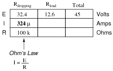
To find this acceptable load resistance value, we can use a table to calculate resistance in the two-resistor series circuit (no diode), inserting the known values of total voltage and dropping resistor resistance, and calculating for an expected load voltage of 12.6 volts:
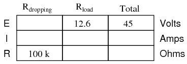
With 45 volts of total voltage and 12.6 volts across the load, we should have 32.4 volts across Rdropping:
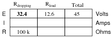
With 32.4 volts across the dropping resistor, and 100 kΩ worth of resistance in it, the current through it will be 324 µA:
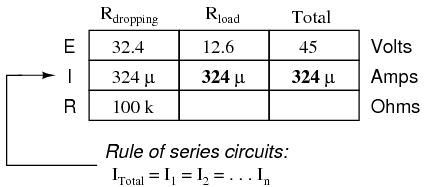
Being a series circuit, the current is equal through all components at any given time:
Calculating load resistance is now a simple matter of Ohm\’s Law (R = E/I), giving us 38.889 kΩ:
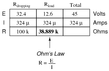
Thus, if the load resistance is exactly 38.889 kΩ, there will be 12.6 volts across it, diode or no diode. Any load resistance smaller than 38.889 kΩ will result in a load voltage less than 12.6 volts, diode or no diode. With the diode in place, the load voltage will be regulated to a maximum of 12.6 volts for any load resistance greater than 38.889 kΩ.
With the original value of 1 kΩ for the dropping resistor, our regulator circuit was able to adequately regulate voltage even for a load resistance as low as 500 Ω. What we see is a tradeoff between power dissipation and acceptable load resistance.
The higher-value dropping resistor gave us less power dissipation, at the expense of raising the acceptable minimum load resistance value. If we wish to regulate voltage for low-value load resistances, the circuit must be prepared to handle higher power dissipation.
How Zener Diode do Voltage Regulation?
Zener diodes regulate voltage by acting as complementary loads, drawing more or less current as necessary to ensure a constant voltage drop across the load.
This is analogous to regulating the speed of an automobile by braking rather than by varying the throttle position: not only is it wasteful, but the brakes must be built to handle all the engine\’s power when the driving conditions don\’t demand it.
Despite this fundamental inefficiency of design, zener diode regulator circuits are widely employed due to their sheer simplicity. In high-power applications where the inefficiencies would be unacceptable, other voltage-regulating techniques are applied. But even then, small zener-based circuits are often used to provide a “reference” voltage to drive a more efficient amplifier circuit controlling the main power.
Common Zener Diode Voltages
Zener diodes are manufactured in standard voltage ratings listed in Table below. The table “Common zener diode voltages” lists common voltages for 0.3W and 1.3W parts.
The wattage corresponds to die and package size, and is the power that the diode may dissipate without damage.
Common zener diode voltages
| 0.5W | ||||||
| 2.7V | 3.0V | 3.3V | 3.6V | 3.9V | 4.3V | 4.7V |
| 5.1V | 5.6V | 6.2V | 6.8V | 7.5V | 8.2V | 9.1V |
| 10V | 11V | 12V | 13V | 15V | 16V | 18V |
| 20V | 24V | 27V | 30V | |||
| 1.3W | ||||||
| 4.7V | 5.1V | 5.6V | 6.2V | 6.8V | 7.5V | 8.2V |
| 9.1V | 10V | 11V | 12V | 13V | 15V | 16V |
| 18V | 20V | 22V | 24V | 27V | 30V | 33V |
| 36V | 39V | 43V | 47V | 51V | 56V | 62V |
| 68V | 75V | 100V | 200V |
Zener Diode Clipper
A clipping circuit which clips the peaks of waveform at approximately the zener voltage of the diodes.
The circuit of Figure below has two zeners connected series opposing to symmetrically clip a waveform at nearly the Zener voltage. The resistor limits current drawn by the zeners to a safe value.
 |
*SPICE 03445.eps D1 4 0 diode D2 4 2 diode R1 2 1 1.0k V1 1 0 SIN(0 20 1k) .model diode d bv=10 .tran 0.001m 2m .end |
Zener diode clipper:
The zener breakdown voltage for the diodes is set at 10 V by the diode model parameter “bv=10” in the spice net list in Figure above. This causes the zeners to clip at about 10 V.
The back-to-back diodes clip both peaks. For a positive half-cycle, the top zener is reverse biased, breaking down at the zener voltage of 10 V. The lower zener drops approximately 0.7 V.
since it is forward biased. Thus, a more accurate clipping level is 10 0.7=10.7V. Similar negative half-cycle clipping occurs a -10.7 V. (Figure below) shows the clipping level at a little over ±10 V.

Zener diode clipper: v(1) input is clipped at waveform v(2).
Review
Zener diodes are designed to be operated in reverse-bias mode, providing a relatively low, stable breakdown, or zener voltage at which they begin to conduct substantial reverse current.
A zener diode may function as a voltage regulator by acting as an accessory load, drawing more current from the source if the voltage is too high, and less if it is too low.
