Because a transistor’s collector current is proportionally limited by its base current, it can be used as a sort of current-controlled switch. A relatively small flow of electrons sent through the base of the transistor has the ability to exert control over a much larger flow of electrons through the collector.
BJT as a Switch
Suppose we had a lamp that we wanted to turn on and off with a switch. Such a circuit would be extremely simple as in the Figure below(a).
For the sake of illustration, let\’s insert a transistor in place of the switch to show how it can control the flow of electrons through the lamp.
Remember that the controlled current through a transistor must go between collector and emitter. Since it is the current through the lamp that we want to control, we must position the collector and emitter of our transistor where the two contacts of the switch were.
We must also make sure that the lamp\’s current will move against the direction of the emitter arrow symbol to ensure that the transistor\’s junction bias will be correct as in Figure below(b).

(a) mechanical switch, (b) NPN transistor switch, (c) PNP transistor switch.
A PNP transistor could also have been chosen for the job. Its application is shown in Figure above(c).
The choice between NPN and PNP is really arbitrary. All that matters is that the proper current directions are maintained for the sake of correct junction biasing (electron flow going against the transistor symbol\’s arrow).
Going back to the NPN transistor in our example circuit, we are faced with the need to add something more so that we can have base current. Without a connection to the base wire of the transistor, base current will be zero, and the transistor cannot turn on, resulting in a lamp that is always off.
Remember that for an NPN transistor, base current must consist of electrons flowing from emitter to base (against the emitter arrow symbol, just like the lamp current).
Perhaps the simplest thing to do would be to connect a switch between the base and collector wires of the transistor as in Figure below (a).

Transistor: (a) cutoff, lamp off; (b) saturated, lamp on.
Cutoff vs Saturated Transistors
If the switch is open as in Figure above (a), the base wire of the transistor will be left “floating” (not connected to anything) and there will be no current through it. In this state, the transistor is said to be cutoff.
If the switch is closed as in Figure above (b), electrons will be able to flow from the emitter through to the base of the transistor, through the switch, up to the left side of the lamp, back to the positive side of the battery.
This base current will enable a much larger flow of electrons from the emitter through to the collector, thus lighting up the lamp. In this state of maximum circuit current, the transistor is said to be saturated.
Of course, it may seem pointless to use a transistor in this capacity to control the lamp. After all, we\’re still using a switch in the circuit, aren\’t we? If we\’re still using a switch to control the lamp — if only indirectly — then what\’s the point of having a transistor to control the current? Why not just go back to our original circuit and use the switch directly to control the lamp current?
Why Use a Transistor to Control Current?
Two points can be made here, actually. First is the fact that when used in this manner, the switch contacts need only handle what little base current is necessary to turn the transistor on; the transistor itself handles most of the lamp\’s current.
This may be an important advantage if the switch has a low current rating: a small switch may be used to control a relatively high-current load. More importantly, the current-controlling behavior of the transistor enables us to use something completely different to turn the lamp on or off.
Consider Figure below, where a pair of solar cells provides 1 V to overcome the 0.7 VBE of the transistor to cause base current flow, which in turn controls the lamp.

Solar cell serves as light sensor.
Or, we could use a thermocouple (many connected in series) to provide the necessary base current to turn the transistor on in Figure below.
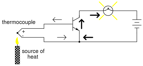
A single thermocouple provides less than 40 mV. Many in series could produce in excess of the 0.7 V transistor VBE to cause base current flow and consequent collector current to the lamp.
Even a microphone (Figure below) with enough voltage and current (from an amplifier) output could turn the transistor on, provided its output is rectified from AC to DC so that the emitter-base PN junction within the transistor will always be forward-biased:

Amplified microphone signal is rectified to DC to bias the base of the transistor providing a larger collector current.
The point should be quite apparent by now: any sufficient source of DC current may be used to turn the transistor on, and that source of current only need be a fraction of the current needed to energize the lamp.
Here we see the transistor functioning not only as a switch, but as a true amplifier: using a relatively low-power signal to control a relatively large amount of power. Please note that the actual power for lighting up the lamp comes from the battery to the right of the schematic.
It is not as though the small signal current from the solar cell, thermocouple, or microphone is being magically transformed into a greater amount of power. Rather, those small power sources are simply controlling the battery\’s power to light up the lamp.
Review
Transistors may be used as switching elements to control DC power to a load. The switched (controlled) current goes between emitter and collector; the controlling current goes between emitter and base.
When a transistor has zero current through it, it is said to be in a state of cutoff (fully nonconducting).
When a transistor has maximum current through it, it is said to be in a state of saturation (fully conducting).
