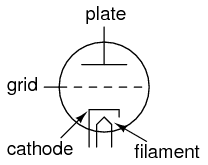
De Forest\’s Audion tube came to be known as the triode tube, because it had three elements: filament, grid, and plate (just as the “di” in the name diode refers to two elements, filament and plate).
Later developments in diode tube technology led to the refinement of the electron emitter: instead of using the filament directly as the emissive element, another metal strip called the cathode could be heated by the filament.
Triode
This refinement was necessary in order to avoid some undesired effects of an incandescent filament as an electron emitter.
First, a filament experiences a voltage drop along its length, as current overcomes the resistance of the filament material and dissipates heat energy. This meant that the voltage potential between different points along the length of the filament wire and other elements in the tube would not be constant.
For this and similar reasons, alternating current used as a power source for heating the filament wire would tend to introduce unwanted AC “noise” in the rest of the tube circuit.
Furthermore, the surface area of a thin filament was limited at best, and limited surface area on the electron emitting element tends to place a corresponding limit on the tube\’s current-carrying capacity.
The cathode was a thin metal cylinder fitting snugly over the twisted wire of the filament. The cathode cylinder would be heated by the filament wire enough to freely emit electrons, without the undesirable side effects of actually carrying the heating current as the filament wire had to.
Triode Symbol
The tube symbol for a triode with an indirectly-heated cathode looks like this:
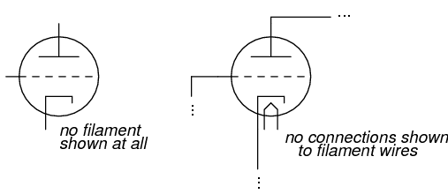
Since the filament is necessary for all but a few types of vacuum tubes, it is often omitted in the symbol for simplicity, or it may be included in the drawing but with no power connections drawn to it:
Triode Amplifier Circuit
A simple triode circuit is shown to illustrate its basic operation as an amplifier:
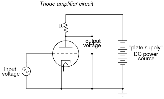
The low-voltage AC signal connected between the grid and cathode alternately suppresses, then enhances the electron flow between cathode and plate. This causes a change in voltage on the output of the circuit (between plate and cathode).
The AC voltage and current magnitudes on the tube\’s grid are generally quite small compared with the variation of voltage and current in the plate circuit.
Thus, the triode functions as an amplifier of the incoming AC signal (taking high-voltage, high-current DC power supplied from the large DC source on the right and “throttling” it by means of the tube\’s controlled conductivity).
In the triode, the amount of current from cathode to plate (the “controlled” current is a function both of grid-to-cathode voltage (the controlling signal) and the plate-to-cathode voltage (the electromotive force available to push electrons through the vacuum).
Unfortunately, neither of these independent variables have a purely linear effect on the amount of current through the device (often referred to simply as the “plate current”). That is, triode current does not necessarily respond in a direct, proportional manner to the voltages applied.
In this particular amplifier circuit the nonlinearities are compounded, as plate voltage (with respect to cathode) changes along with the grid voltage (also with respect to cathode) as plate current is throttled by the tube. The result will be an output voltage waveform that doesn\’t precisely resemble the waveform of the input voltage.
In other words, the quirkiness of the triode tube and the dynamics of this particular circuit will distort the waveshape. If we really wanted to get complex about how we stated this, we could say that the tube introduces harmonics by failing to exactly reproduce the input waveform.
Stray Capacitance
Another problem with triode behavior is that of stray capacitance. Remember that any time we have two conductive surfaces separated by an insulating medium, a capacitor will be formed.
Any voltage between those two conductive surfaces will generate an electric field within that insulating region, potentially storing energy and introducing reactance into a circuit.
Such is the case with the triode, most problematically between the grid and the plate. It is as if there were tiny capacitors connected between the pairs of elements in the tube:
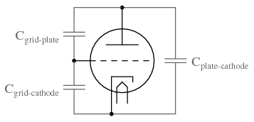
Now, this stray capacitance is quite small, and the reactive impedances usually high. Usually, that is, unless radio frequencies are being dealt with.
As we saw with De Forest\’s Audion tube, radio was probably the prime application for this new technology, so these “tiny” capacitances became more than just a potential problem. Another refinement in tube technology was necessary to overcome the limitations of the triode.
