Half-Adder

As a first example of useful combinational logic, let’s build a device that can add two binary digits together. We can quickly calculate what the answers

should be:

0 + 0 = 0          0 + 1 = 1          1 + 0 = 1          1 + 1 = 102

So we well need two inputs (a and b) and two outputs. The low order output will be called Σ because it represents the sum, and the high order output will be called Cout because it represents the carry out. The truth table is

Half-Adder Truth Table

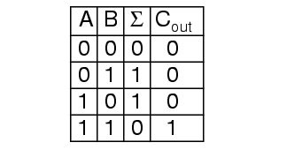
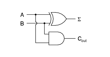
Simplifying boolean equations or making some Karnaugh map will produce the same circuit shown below, but start by looking at the results.

The Σ column is our familiar XOR gate, while the Cout column is the AND gate. This device is called a half-adder for reasons that will make sense in the next section.
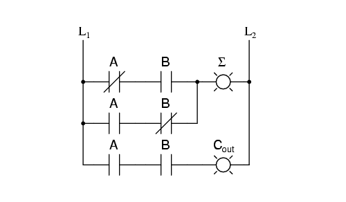
or in ladder logic

You've successfully subscribed !
Share

Recent Articles

Introduction to AC Motors

Initially, AC motors were constructed like DC motors. Numerous problems were encountered due to changing…

4 years ago

AC Instrumentation Transducers

Learn about the AC Instrumentation Transducers like Potentiometer, LVDT, RVDT, Synchro, and Capacitive Transducers.

4 years ago

AC Bridge Circuits

AC bridge circuit unknown impedance is balanced by a standard impedance of similar type on…

4 years ago

Power Quality Measurement

Power Quality is the general term given to represent an AC power system freedom from harmonic…

4 years ago

Power Measurement

Hall effect - Voltage is proportional to current and strength of the perpendicular magnetic field.…

4 years ago

Frequency and Phase Measurement

Learn about the Frequency and Phase Measurement from our free online electronics and electrical engineering…

4 years ago