It is sometimes useful in logic circuits to have a multivibrator which changes state only when certain conditions are met, regardless of its S and R input states. The conditional input is called the enable, and is symbolized by the letter E.
Study the following example to see how this works:
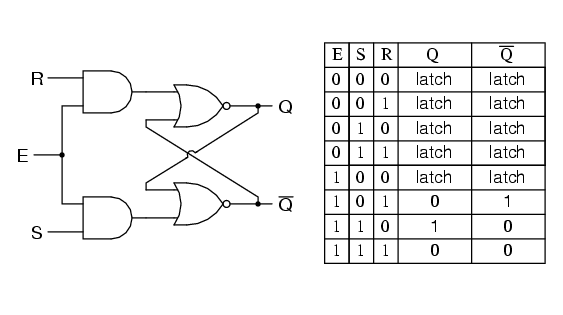
When the E=0, the outputs of the two AND gates are forced to 0, regardless of the states of either S or R.
Consequently, the circuit behaves as though S and R were both 0, latching the Q and not-Q outputs in their last states. Only when the enable input is activated (1) will the latch respond to the S and R inputs. Note the identical function in ladder logic:
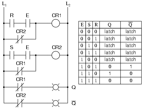
A practical application of this might be the same motor control circuit (with two normally-open push button switches for start and stop), except with the addition of a master lockout input (E) that disables both push buttons from having control over the motor when its low (0).
Once again, these multivibrator circuits are available as prepackaged semiconductor devices, and are symbolized as such:
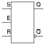
It is also common to see the enable input designated by the letters “EN” instead of just “E.”
Summary
The enable input on a multivibrator must be activated for either S or R inputs to have any effect on the output state.
This enable input is sometimes labeled “E”, and other times as “EN”.
