Inst ToolsInst ToolsInst Tools
  • Courses
  • Automation
    • PLC
    • Control System
    • Safety System
    • Communication
    • Fire & Gas System
  • Instrumentation
    • Design
    • Pressure
    • Temperature
    • Flow
    • Level
    • Vibration
    • Analyzer
    • Control Valve
    • Switch
    • Calibration
    • Erection & Commissioning
  • Interview
    • Instrumentation
    • Electrical
    • Electronics
    • Practical
  • Q&A
    • Instrumentation
    • Control System
    • Electrical
    • Electronics
    • Analog Electronics
    • Digital Electronics
    • Power Electronics
    • Microprocessor
  • Request
Search
  • Books
  • Software
  • Projects
  • Process
  • Tools
  • Basics
  • Formula
  • Power Plant
  • Root Cause Analysis
  • Electrical Basics
  • Animation
  • Standards
  • 4-20 mA Course
  • Siemens PLC Course
Reading: Thermocouple Terminal block Questions
Share
Font ResizerAa
Inst ToolsInst Tools
Font ResizerAa
  • Courses
  • Design
  • PLC
  • Interview
  • Control System
Search
  • Courses
  • Automation
    • PLC
    • Control System
    • Safety System
    • Communication
    • Fire & Gas System
  • Instrumentation
    • Design
    • Pressure
    • Temperature
    • Flow
    • Level
    • Vibration
    • Analyzer
    • Control Valve
    • Switch
    • Calibration
    • Erection & Commissioning
  • Interview
    • Instrumentation
    • Electrical
    • Electronics
    • Practical
  • Q&A
    • Instrumentation
    • Control System
    • Electrical
    • Electronics
    • Analog Electronics
    • Digital Electronics
    • Power Electronics
    • Microprocessor
  • Request
Follow US
All rights reserved. Reproduction in whole or in part without written permission is prohibited.
Inst Tools > Blog > Practical Questions > Thermocouple Terminal block Questions

Thermocouple Terminal block Questions

Last updated: April 25, 2019 11:50 am
Editorial Staff
Practical Questions
1 Comment
Share
3 Min Read
SHARE

When a type “T” thermocouple (copper/constantan) is connected to a voltmeter made of copper wires, two active junctions are formed: one at the point of measurement (the measurement junction) and one at a terminal near the voltmeter (the reference junction). The copper-to-copper junction at the top screw of the terminal block is of no consequence because it is a junction of identical metals, and as such generates no thermoelectric voltage:

Thermocouple Questions

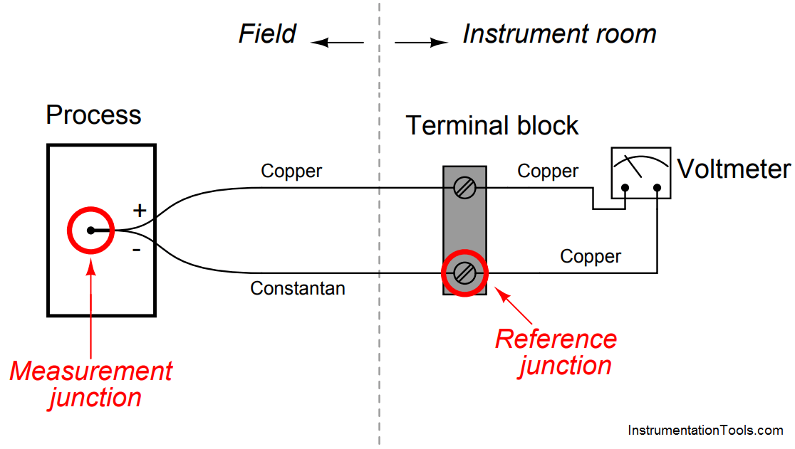
The amount of voltage sensed by the voltmeter in this thermocouple circuit is equal to the difference in voltages produced by the measurement and reference junctions:

Emeter = Emeas − Eref

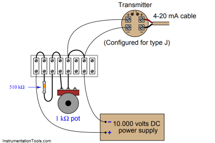
Now consider a type “J” thermocouple connected to a copper-wire voltmeter. Here we see there are not two but three active junctions of dissimilar metals:

Thermocouple Problems

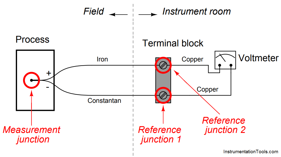
Upon first observation it would appear this circuit is more complicated than the type “T” thermocouple circuit, owing to the existence of the additional dissimilar-metal junction. However, a principle called the Law of Intermediate Metals allows us to consider the two reference junctions (iron-copper and constantancopper) as electrically equivalent to a single reference junction of iron-constantan, such that the type “J” thermocouple circuit becomes just as simple as the type “T” circuit with one measurement junction and one reference junction in opposition to each other.

Explain what the Law of Intermediate Metals is, and how it may be used to simplify the two active reference junctions of the type “J” circuit.

Also, explain why it is important that the terminal block be isothermal in nature.

Answer :

The Law of Intermediate Metals tells us that a series chain of dissimilar metal junctions at the same temperature are electrically equivalent to a single junction comprised of the outer two metals (ignoring all the intermediate metal types between) at that temperature.

Thus, the iron-copper-constantan reference junction pair is electrically equivalent to a single iron-constantan reference junction, so long as both screw terminals are at the same temperature (isothermal). This principle renders the meter’s metal type irrelevant.

Don't Miss Our Updates
Be the first to get exclusive content straight to your email.
We promise not to spam you. You can unsubscribe at any time.
Invalid email address
You've successfully subscribed !

Continue Reading

How to Draw a Schematic Diagram ?
Process Control High Level Alarm Fault Analysis
Pressure Switch Questions
Electric-driven Air Compressor Troubleshooting
Liquid Level Measurement using Pressure Transmitter Questions
Displacer Type Density Transmitter Question
Share This Article
Facebook Whatsapp Whatsapp LinkedIn Copy Link
Share
1 Comment
  • Amar kumar sahu says:
    April 17, 2018 at 10:49 am

    Pls this app Hindi language’s option for reading pls sir

    Reply

Leave a Reply Cancel reply

Your email address will not be published. Required fields are marked *

Stay Connected

128.3kFollowersLike
69.1kFollowersFollow
210kSubscribersSubscribe
38kFollowersFollow

Categories

Explore More

Instrument Salesperson Question
Sketch a Ladder Diagram for PLC to Energize the Lamp
Practical Process Control System Questions & Answers – 5
Tank uses 3 Pressure Transmitters to Measure Level & Density
Identify Faults in PID Control Loop
Simple High Level Indicator Circuit
Re-calibrate the Foxboro DP Pneumatic Transmitter
Purpose of Stop in a Pressure Measuring Instrument

Keep Learning

Type E thermocouple

Type E thermocouple Calculations

Steam Eductor Question

Steam Eductor Question

Differential Pressure Measurement across Baghouse

Differential Pressure Measurement across Baghouse

Simple Pressure Transmitter Circuit

Pressure Transmitter using Potentiometer and Diaphragm

DP transmitter Errors

DP Transmitter Calibration Errors

Signal Strength of Guided-wave Radar Level Instrument

Signal Strength of Guided-wave Radar Level Instrument

Double Block and Bleed Valves Opening or Closing Sequence

Double Block and Bleed Valves Opening or Closing Sequence

steam heat exchanger

Practical Process Control System Questions & Answers – 9

Learn More

Use PLC Flags as Integrity Checks

#4 PLC Best Practices – Use PLC Flags as Integrity Checks

Series Parallel Circuit Analysis

Series – Parallel Circuit Analysis

Power Electronics Objective Questions

AC Voltage Controllers Quiz

Difference Between Combinational Circuit and Sequential Circuit

Difference Between Combinational and Sequential Circuit

Single Phase Half-controlled Rectifier RL Load With FD

Phase-Controlled Half-Wave Rectifier With Freewheeling Diode

Electrical Machines Objective Questions

Electrical Machines MCQ Series 21

Level Flow Cascade Control Pumping Station

Introduction to Wastewater Treatment Works and Pumping Station

Measurement and Instrumentation Objective Questions

Measurements & Instrumentation Quiz – Set 10

Menu

  • About
  • Privacy Policy
  • Copyright

Quick Links

  • Learn PLC
  • Helping Hand
  • Part Time Job

YouTube Subscribe

Follow US
All rights reserved. Reproduction in whole or in part without written permission is prohibited.
Welcome Back!

Sign in to your account

Username or Email Address
Password

Lost your password?