Inst ToolsInst ToolsInst Tools
  • Courses
  • Automation
    • PLC
    • Control System
    • Safety System
    • Communication
    • Fire & Gas System
  • Instrumentation
    • Design
    • Pressure
    • Temperature
    • Flow
    • Level
    • Vibration
    • Analyzer
    • Control Valve
    • Switch
    • Calibration
    • Erection & Commissioning
  • Interview
    • Instrumentation
    • Electrical
    • Electronics
    • Practical
  • Q&A
    • Instrumentation
    • Control System
    • Electrical
    • Electronics
    • Analog Electronics
    • Digital Electronics
    • Power Electronics
    • Microprocessor
  • Request
Search
  • Books
  • Software
  • Projects
  • Process
  • Tools
  • Basics
  • Formula
  • Power Plant
  • Root Cause Analysis
  • Electrical Basics
  • Animation
  • Standards
  • 4-20 mA Course
  • Siemens PLC Course
Reading: Temperature Coefficient of Resistance (α)
Share
Notification Show More
Font ResizerAa
Inst ToolsInst Tools
Font ResizerAa
  • Courses
  • Design
  • PLC
  • Interview
  • Control System
Search
  • Courses
  • Automation
    • PLC
    • Control System
    • Safety System
    • Communication
    • Fire & Gas System
  • Instrumentation
    • Design
    • Pressure
    • Temperature
    • Flow
    • Level
    • Vibration
    • Analyzer
    • Control Valve
    • Switch
    • Calibration
    • Erection & Commissioning
  • Interview
    • Instrumentation
    • Electrical
    • Electronics
    • Practical
  • Q&A
    • Instrumentation
    • Control System
    • Electrical
    • Electronics
    • Analog Electronics
    • Digital Electronics
    • Power Electronics
    • Microprocessor
  • Request
Follow US
All rights reserved. Reproduction in whole or in part without written permission is prohibited.
Inst Tools > Blog > Temperature Measurement > Temperature Coefficient of Resistance (α)

Temperature Coefficient of Resistance (α)

Last updated: May 12, 2019 5:56 pm
Editorial Staff
Temperature Measurement
No Comments
Share
4 Min Read
SHARE

A Resistive Temperature Detector (RTD) is a special temperature-sensing element made of fine metal wire, the electrical resistance of which changes with temperature as approximated by the following formula:

Temperature Coefficient of Resistance (α)

Where,
RT = Resistance of RTD at given temperature T (ohms)
Rref = Resistance of RTD at the reference temperature Tref (ohms)
α = Temperature coefficient of resistance (ohms per ohm/degree)

The following example shows how to use this formula to calculate the resistance of a “100 ohm” platinum RTD with a temperature coefficient value of 0.00392 at a temperature of 35 degrees Celsius:

RT = 100 [1 + (0.00392)(35o C − 0o C)]
RT = 100 [1 + 0.1372]
RT = 100 [1.1372]
RT = 113.72

Due to nonlinearities in the RTD’s behavior, this linear RTD formula is only an approximation. A better approximation is the Callendar-van Dusen formula, which introduces second, third, and fourth-degree terms for a better fit:

RT = Rref (1 + AT + BT2 − 100CT3 + CT4) for temperatures ranging −200 oC < T < 0 oC and

RT = Rref (1+AT +BT2) for temperatures ranging 0 oC < T < 661 oC,

both assuming Tref = 0 oC. The A, B, and C coefficients vary with the specific type of RTD, equivalent in role to α in the linear RTD formula.

Water’s melting/freezing point is the standard reference temperature for most RTDs. Here are some typical values of α for common metals:

  • Nickel = 0.00672  Ω/ΩoC
  • Tungsten = 0.0045  Ω/ΩoC
  • Silver = 0.0041  Ω/ΩoC
  • Gold = 0.0040  Ω/ΩoC
  • Platinum = 0.00392  Ω/ΩoC
  • Copper = 0.0038  Ω/ΩoC

As mentioned previously, platinum is a common wire material for industrial RTD construction. The alpha (α) value for platinum varies according to the alloying of the metal. For “reference grade” platinum wire, the most common alpha value is 0.003902. Industrial-grade platinum alloy RTD wire is commonly available in two different coefficient values: 0.00385 (the “European” alpha value) and 0.00392 (the “American” alpha value), of which the “European” value of 0.00385 is most commonly used (even in the United States!).

An alternative to mathematically predicting the resistance of an RTD is to simply look up its predicted resistance versus temperature in a table of values published for that RTD type. Tables capture the nuances of an RTD’s non-linearity without adding any mathematical complexity: simply look up the resistance corresponding to a given temperature, or vice-versa. If a value falls between two nearest entries in the table, you may interpolate the find the desired value, regarding the two nearest table entries as end-points defining a line segment, calculating the point you desire along that line.

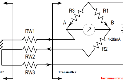
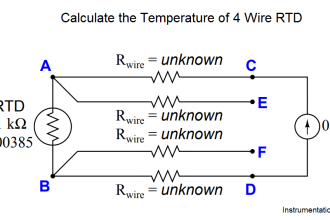
100 Ω is a very common reference resistance (Rref at 0 degrees Celsius) for industrial RTDs. 1000 Ω is another common reference resistance, and some industrial RTDs have reference resistances as low as 10 Ω . Compared to thermistors with their tens or even hundreds of thousands of ohms’ resistance, an RTD’s resistance is comparatively small. This can cause problems with measurement, since the wires connecting an RTD to its ohmmeter possess their own resistance, which will be a more substantial percentage of the total circuit resistance than for a thermistor.

Credits : Tony R. Kuphaldt – Creative Commons Attribution 4.0 License

Don't Miss Our Updates
Be the first to get exclusive content straight to your email.
We promise not to spam you. You can unsubscribe at any time.
Invalid email address
You've successfully subscribed !

Continue Reading

Thermostat – Types, Working Principle, Advantages, Applications
Calibration of Temperature Sensor with Indicator
Manually Interpreting Thermocouple Voltages
Thermocouple Extension and Compensating Cables
Multiple Position Calibration of Temperature Chamber
RTD Calibration Procedure
Share This Article
Facebook Whatsapp Whatsapp LinkedIn Copy Link
Share
Leave a Comment

Leave a Reply Cancel reply

Your email address will not be published. Required fields are marked *

Stay Connected

128.3kFollowersLike
69.1kFollowersFollow
210kSubscribersSubscribe
38kFollowersFollow

Categories

Explore More

Installation Precautions of Thermocouple and RTD
Temperature Measurement Objective Questions
Thermocouples Burnout detection
Why have been limits imposed on the frequency ratio for thermowells?
Components of RTD
Thermocouples Green Rot Effect
Questions on Thermocouple and Pyrometer
Spiral Bimetallic Thermometer Principle

Keep Learning

thermocouple types

What is a Thermocouple ?

Probe Thermometer

What is a Probe Thermometer? How to Calibrate and Use it?

Two Wire RTD Lead Wire Resistance Error

Temperature Error of 2-Wire, 3-Wire & 4-Wire RTD

Insulation of Thermowell

Facts on Thermowell Insulation Thickness

Thermocouple Temperature Measurements Errors

Thermocouple Temperature Measurement Errors

RTD installed after the Orifice Plate

Why RTD installed after the Orifice Plate ?

Temperature Transmitter Foundation Fieldbus Configuration

Foundation Fieldbus Temperature Transmitter Configuration

Liquid In Glass Thermometers

Liquid In Glass Thermometer Principle

Learn More

Difference Between Earth and Neutral

Difference Between Earth and Neutral

Instrumentation Technical Interview Questions and Answers

Instrumentation Technical Interview Questions and Answers

Diaphragm

Diaphragms

Pneumatic and Hydraulic Projects

200 Pneumatic and Hydraulic Projects List

How to Calculate Network Speed?

Factors to Consider When Calculating Network Speed

Liquid management using PLC programming

PLC Programming for Loss in Weight Liquid Systems

Applications of SCADA

Steam Turbine Driven Centrifugal Compressors Leak due to Broken Instrument

Steam Turbine Driven Centrifugal Compressors Leak due to Broken Instrument

Menu

  • About
  • Privacy Policy
  • Copyright

Quick Links

  • Learn PLC
  • Helping Hand
  • Part Time Job

YouTube Subscribe

Follow US
All rights reserved. Reproduction in whole or in part without written permission is prohibited.
Welcome Back!

Sign in to your account

Username or Email Address
Password

Lost your password?