For decades, process instrumentation specifiers have faced the decision whether to use a switch or a continuous transmitter for a given application. Either type of instrument can be used to effectively control industrial processes and protect equipment and personnel — and each has associated pros and cons. Application specifics typically drive decision-making, dictating which approach is most effective from performance, cost and life cycle support perspectives.
At its most basic, a switch acts in a binary fashion, changing state when a pressure, temperature, level or other process variable crosses over some predefined threshold. If the process variable in question can be allowed to vary in the course of normal operation, a simple mechanical switch linked to an on/off valve or pump can effectively and reliably control the process at hand, keeping a tank from running dry or a temperature from climbing too high.
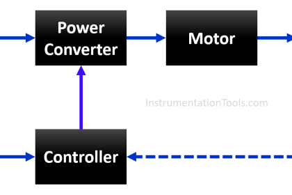
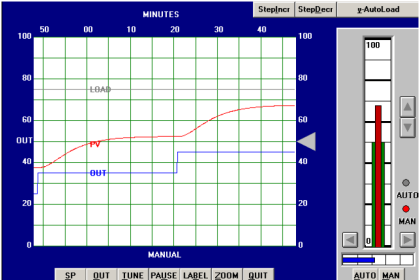
Transmitters, on the other hand, continuously measure and communicate their assigned process variables over a range of values. A transmitter can facilitate on/off control actions similar to those of a switch through configurable discrete outputs within an associated controller. But a continuous transmitter teamed with a modulating control valve or pump with variable speed drive also can be used to implement more subtle (albeit more expensive) control strategies — such as a proportional-integral-derivative (PID) algorithm — to maintain the process variable at a specific value or setpoint.
A third option is the integrated or hybrid switch-transmitter, which combines a continuous transmitter and solid-state switch within a single instrument housing. This approach effectively combines a number of the advantages of both.
Process Requirements
When choosing among these three alternatives, the instrument specifier must first answer three key application-specific questions:
- In the course of normal operation, can the process variable in question be allowed to vary between lower and/or upper limits, or is more precise setpoint control required?
- Beyond the control action itself, is there a need for local display or remote communication and alarming of the process variable in question?
- What are the consequences if the process variable does move outside its intended range? Will equipment damage, excessive downtime or an unsafe condition ensue?
Whether or not precise setpoint control is needed will determine whether a switch or transmitter output is needed to provide the necessary control functionality. If control over a range of setpoints is required, a continuous transmitter will be needed. Just how precisely the process variable must be measured — and controlled — will determine how accurate (i.e., how expensive) the transmitter will need to be.
If there is a need to display or communicate the process variable in question, application of a transmitter also is indicated. A switch by its very nature does not provide a measurement signal output to drive a local display or remote communications. It simply changes state when its threshold is crossed, initiating a discrete (on/off) control action.
Other considerations being equal, however, today’s switch technology can provide extremely reliable, cost-effective control when the process variable need only be controlled within upper and/or lower bounds without the need for remote visibility. The installed costs of a switch are generally less than those of a transmitter of comparable quality. Further, the switch can be expected to last on the order of 40 years whereas a transmitter, because of its electronic componentry, might face a considerably shorter life.
A switch also has the inherent advantages of simplicity: it comes factory-calibrated, is relatively simple to install, requires no power and connects directly to the final control element. No communication with a host controller is required, which can mean response time in as little as 5 milliseconds. Transmitters, on the other hand, typically communicate with final control elements through some sort of host controller — adding complexity, potential points of failure.
When Safety Matters
If adverse consequences such as equipment damage, excessive downtime or an unsafe condition are likely to ensue if the process variable moves beyond its intended range, risk analysis and safety considerations come to the forefront. In these types of applications, the transmitter holds one advantage over the switch in that it’s easier to tell if a transmitter is not working. This is both because of its continuous communications output and the extensive self-diagnostics built into today’s electronic transmitters. While normally quite reliable, there’s no obvious or automatic way to tell if a switch deployed in a protective (non-control) application has failed. To help alleviate this possibility, manual proof tests performed at designated intervals are needed to ensure ongoing switch integrity.
Increasingly, if a process variable excursion represents a significant safety risk or other adverse consequence, a continuous transmitter teamed with a back-up safety switch provides the most robust combination of protection and control, although periodic proof tests of the switch still are needed to ensure continued protection. Additionally, the use of intentionally diverse underlying sensor technologies decreases the likelihood of a common-cause failure of both devices, providing further assurance that if the transmitter and/or controller fails, the process will be brought to a safe state.
And while a separate transmitter and switch provides more secure operation than either instrument by itself, this approach does entail the purchase of two instruments, two process penetrations, and all the attendant effort and expense they represent. For this type of application, the hybrid transmitter/switch represents a more cost-effective yet secure solution: a continuous transmitter and solid-state switch installed together in a single device.
Indeed, the hybrid switch-transmitter addresses all three key application considerations raised above. Like a standalone transmitter, it can provide continuous setpoint control over a range of values as well as drive a local display or remote communications. Further, because the integrated switch and its output are functionally independent of the transmitter and its output, this single instrument configuration provides a more cost-effective alternative for applications where a continuous measurement is needed together with a functionally independent layer of switched protection.
Also Read: Instrumentation Design Gudelines

