In the earlier post, we had seen how to define an order of execution of data and blocks in the function block diagram of Studio 5000. Now in this post, we will define the program or operator control features which are available in this language for some types of blocks. This basically helps the programmer to gain more control over some certain types of blocks which can increase the flexibility of the operating system. It is a unique feature available in Studio 5000.
What is program or operator control in Studio 5000?
Let us see what is the meaning of this feature first. There are some instructions in which a function block will need to be executed both automatically by the program and manually by the user. This means suppose I have a system where the process is waiting for an action to happen. The PLC program is already ready internally to start its command on it. But at the same time, it will require an operator to acknowledge first.
This software provides an option where you can control whether the operator will perform its action first or the PLC program internally. The two actions thus named are called program control and operator control. So, when the function block is in program control, the instruction is controlled by their programmed inputs or the PLC logic. When the function block is in operator control, the instruction is controlled by the inputs that the operator will give.
There are four types of inputs in this feature – ProgProgReq, ProgOperReq, OperProgReq, and OperOperReq. In ProgProgReq, a request is sent by the program to go to program control. In ProgOperReq, a request is sent by the program to go to operator control. In OperProgReq, a request is sent by the operator to go to program control. In OperOperReq, a request is sent by the operator to go to operator control.
Also, one thing to note is that program inputs have a higher priority over operator inputs. So, if both types of inputs are high at the same time, program inputs will be given priority over operator inputs. Also, if you want to check whether the block is in program or operator control, check the output – ProgOper. If this bit is set, then the instruction is in program control. If this bit is reset, then the instruction is in operator control.
Refer to the below image, with highlighted inputs and outputs. This feature is available only in the following blocks – enhanced select (ESEL), totalizer (TOT), enhanced PID (PIDE), ramp/soak (RMPS), discrete 2-state device (D2SD) and discrete 3-state device (D3SD). Let us understand exactly how these features are implemented practically.
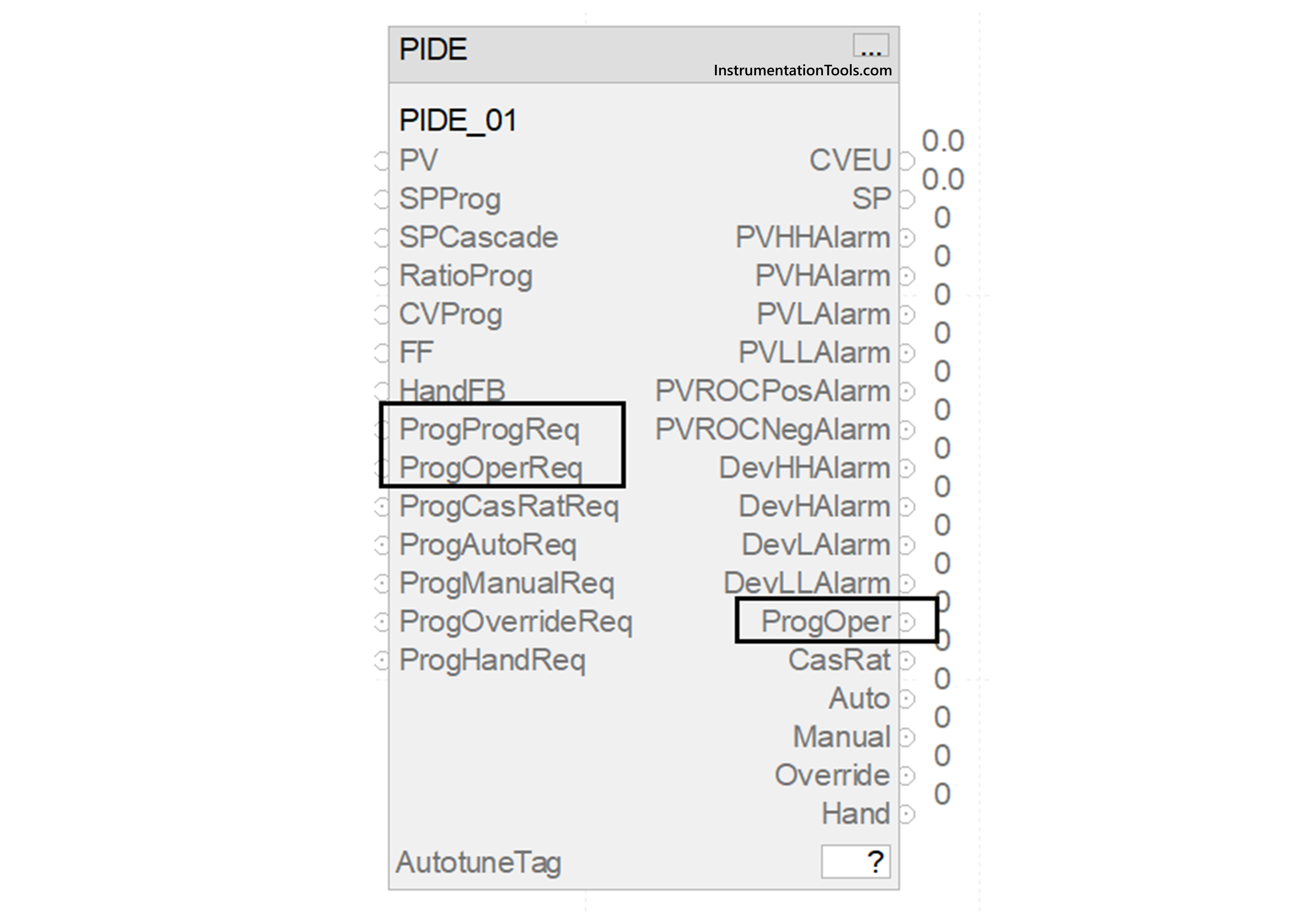
We will take the PID block that was discussed earlier for our reference. Suppose there is a chiller application, which has a compressor working on PID. When the compressor starts, some initial tuning must be done by the program, before any operator can make his inputs. This is for safety purposes and is required to be performed compulsorily. In that case, you can set the bit – ProgProgReq for that set time.
Due to this, the program will take control over PID, irrespective of whether the operator is doing something or not. Then, the bit can be reset and you can now set the bit ProgOperReq or any other bit for operator or program control afterwards. This provides greater flexibility to the programmer in controlling a sequence. Likewise, you can set and reset the other program/operator bits according to your requirements.
In this way, we saw how to define program or operator control in the functional block diagram of Studio 5000. In the next post, we will see how to manage sheets, tags and elements in this language of Studio 5000.
Read Next:
- Network Switch Port Allocation Details
- Failures in Industrial Automation Systems
- HMI Screen Design for Water Treatment Plant
- Motor Starter Logic using Siemens Tia Portal
- FactoryTalk View Import and Export Tutorial
