This PLC Program uses the differentiate UP (DIFU) and differentiate DOWN (DIFD) functions that can be used to teach PLC programming logic to students.
Star-Delta System using 1 Button
The PLC program only uses 1 button. TRIGGER_BUTTON (0.00) button is used to Turn On the system and Turn Off the system.
When the TRIGGER_BUTTON (0.00) button is Pressed once, the system is ON and when the TRIGGER_BUTTON (0.00) button is pressed once again, the system will be OFF.
Logic-1
When the TRIGGER_BUTTON (0.00) button is Pressed, the memory bit SYSTEM_ON (W0.00) will become a HIGH state. Because in this logic, the TRIGGER_BUTTON(0.00) button uses a NO contact Differentiate UP/DIFU type, the memory bit SYSTEM_ON (W0.00) changes to HIGH state when button TRIGGER_BUTTON (0.00) changes from LOW state to HIGH state.
When the memory bit SYSTEM_ON (W0.00) changes to a HIGH state, the output STAR_MODE (100.00) will be ON and the system will RUN in STAR mode.
After 5 seconds the system will change to DELTA mode, Output DELTA_MODE (100.01) becomes ON, and Output STAR_MODE (100.00) changes to OFF.
Logic-2
When the TRIGGER_BUTTON (0.00) button is Released, the memory bit IR_1 (W0.01) will become a HIGH state. Because in this logic, the TRIGGER_BUTTON (0.00) button uses a NO contact Differentiate DOWN/DIFD type, the memory bit IR_1 (W0.01) changes to the HIGH state when button TRIGGER_BUTTON (0.00) changes from the HIGH state to LOW state.
Logic-3
Memory bit IR_2 (W0.02) is used as an Interlock to Turn Off memory bit SYSTEM_ON (W0.00). So when the TRIGGER_BUTTON (0.00) button is Pressed again, the system will be OFF.
PLC I/O Details
| Comment | Input (I) | Output(Q) | TIMER | Word Memory |
| TRIGGER_BUTTON | 0.00 | |||
| STAR_MODE | 100.00 | |||
| DELTA_MODE | 100.01 | |||
| SYSTEM_ON | W0.00 | |||
| IR_1 | W0.01 | |||
| IR_2 | W0.02 | |||
| TIMER_CUTOFF | T0000 |
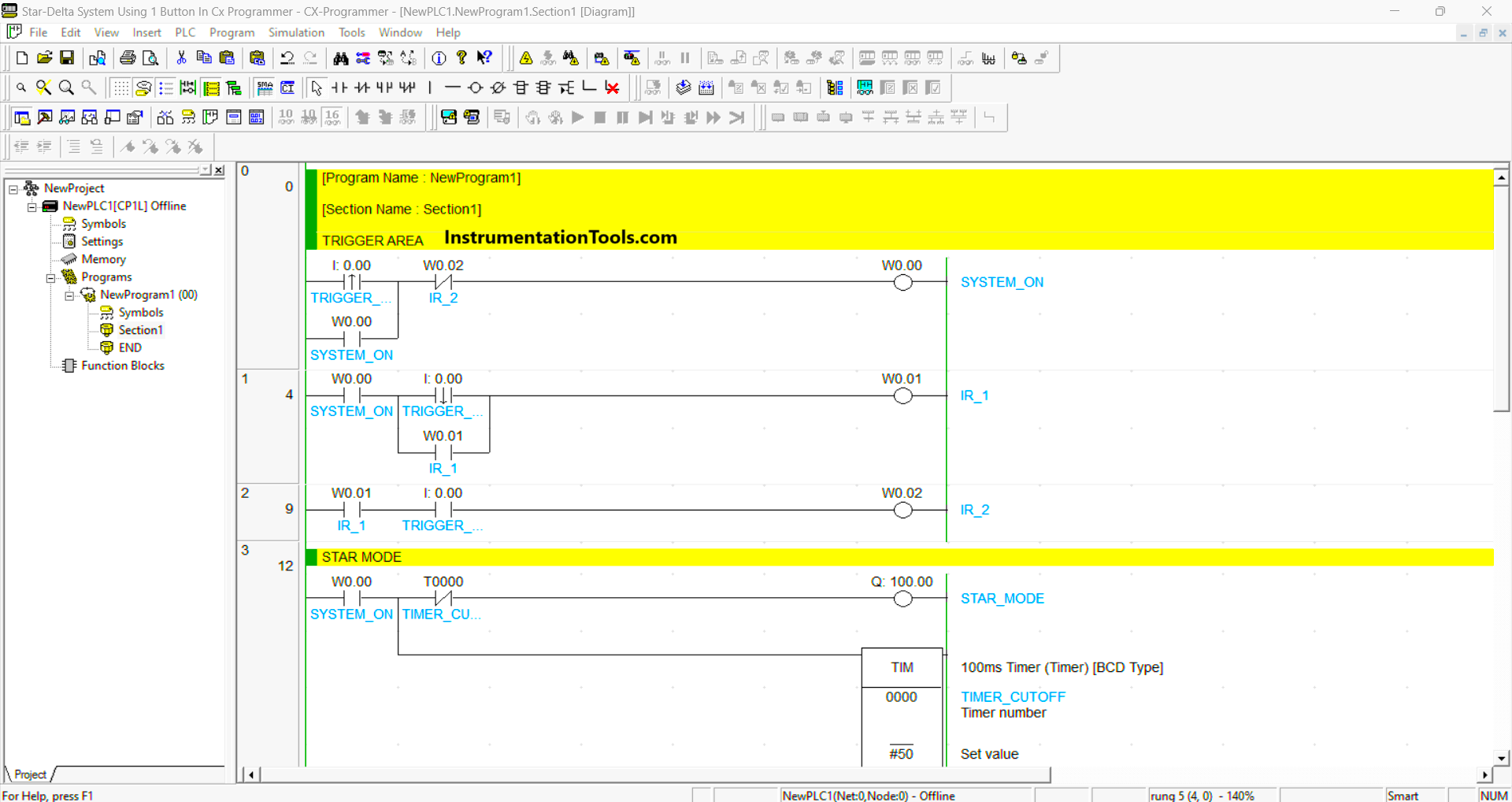
PLC Programming
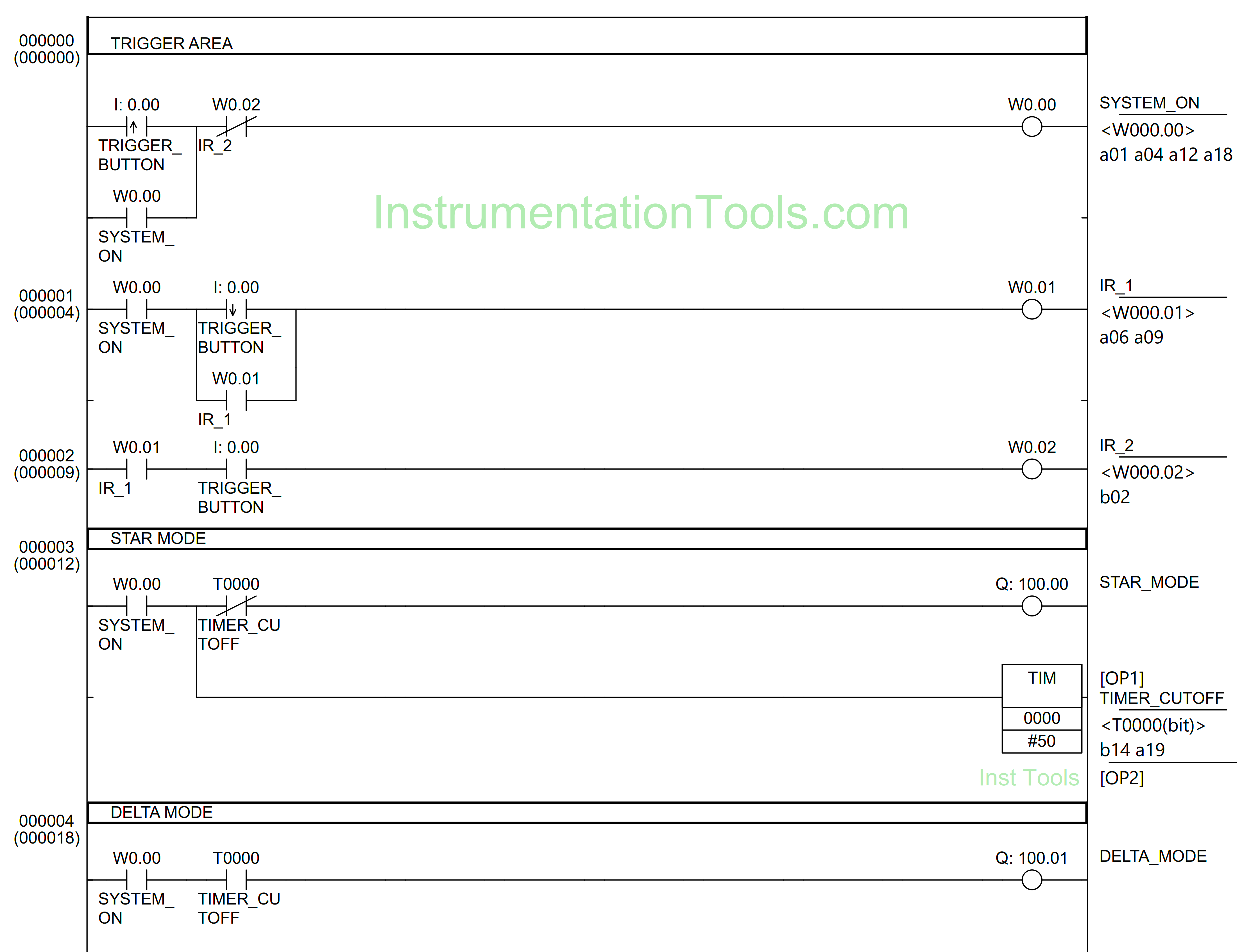
RUNG 0 (TRIGGER AREA)
In this Rung, when the TRIGGER_BUTTON (0.00) button is pressed, the memory bit SYSTEM_ON (W0.00) will become a HIGH state Because it uses Latching, the memory bit SYSTEM_ON (W0.00) remains in the HIGH state even though the TRIGGER_BUTTON (0.00) button is only Active for a moment.
The memory bit SYSTEM_ON (W0.00) will be in the LOW state when the NC contact of memory bit IR_2 (W0.02) is in the HIGH state.
RUNG 1
In this Rung, when the NO contact of memory bit SYSTEM_ON (W0.00) in the HIGH state and the TRIGGER_BUTTON (0.00) button is Released, the memory bit IR_1 (W0.01) will become to HIGH state. Because it uses Latching, the memory bit IR_1 (W0.01) remains in the HIGH state even though the TRIGGER_BUTTON (0.00) button is only Active for a moment.
RUNG 2
The memory bit IR_2 (W0.02) will be in the HIGH state when the NO contact of memory bit IR_1 (W0.01) in the HIGH state and the TRIGGER_BUTTON (0.00) button is Pressed.
RUNG 3 (STAR MODE)
When the NO contact of memory bit SYSTEM_ON(W0.00) in the HIGH state, the STAR_MODE (100.00) output will be ON, and the TIMER_CUTOFF (T0000) timer Starts counting up to 5 seconds.
When the timer TIMER_CUTOFF (T0000) finishes counting, the STAR_MODE (100.00) output becomes OFF.
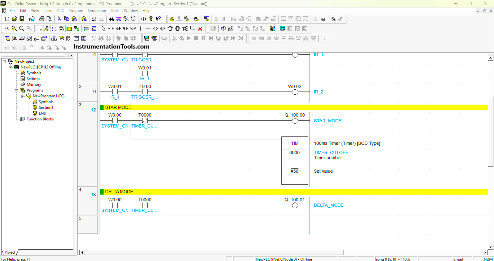
RUNG 4 (DELTA MODE)
The DELTA_MODE (100.01) output will be ON when the NO contact of memory bit SYSTEM_ON (W0.00) and the timer TIMER_CUTOFF (T0000) in HIGH state.
Read Next:
- PLC Product Sticker Machine with Weighing
- Automatic Exhaust Fan XG5000 PLC Program
- Perfume Mixing and Filling System PLC Logic
- Product Painting with Omron PLC Program
- Attendance System Program in Omron PLC


Hi,
Could you please tell me what is the name of the software used in your articles, to draw ladder diagrams ?
Thanks,
Kind regards,
68cme