When you are working on industrial automation projects, there are a lot of standard devices, cables, and systems which are required to be defined properly according to their identifications. For this, one parameter which is used to help the engineers is color. Colors help to define a standard function of the device or system. So, if you are well versed with the color definitions, you can identify, design and maintain the system efficiently and reliably. In this post, we will see the colors used in industrial automation.
Benefits of industrial business color coding
There are a lot of different types of wires, devices, and instruments used in industrial automation which often confuses an operator. You may have seen how bomb diffusers identify the wires in a bomb and cut them correctly to defuse the bomb. This was possible due to standard color wires used in bombs, and helps them to identify their use. In the same way, when you are designing, controlling or maintaining an automation project, colors will help the operators to work with them easily.
Practically, color codes are updated by international bodies once every three or five years, but it is mostly continued (varies only according to compulsory requirements). It makes troubleshooting easier for the engineers, as they will just see the color and know what is their use here. Also, for industrial safety, various hazards and disasters are given colors according to their levels. Due to this, the operators can find it easy to notice them from a distance and work accordingly.
Cable colors in industrial automation
- For DC currents – Red or white is the color used for positive wires, with black or blue as the colors used for negative wires.
- For AC currents – Light blue is the preferred color for neutral wires, with black, brown, grey, and white (usually for lower voltages), red, yellow, dark blue, and violet for phase wires.
- For earthing wires – Yellow and green color mixture is the standard one for earthing indications.
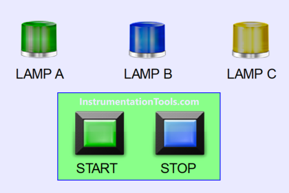
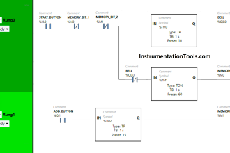
HMI colors in PLC automation systems
- To indicate that the system is stopped, green/red color is used. This indicates to the operator that he can start the system (depending on your country or standard).
- To indicate that the system is running, red/green is used. This indicates to the operator that he can stop the system (depending on your country or standard).
- To indicate that the system has tripped, yellow is used.
- To indicate that the system is currently disabled and not taken into operation right now, grey is used. It shows that the operator needs to enable that device, which can then be started or stopped.
- Red color can also be used as a danger sign, like emergency buttons or critical areas of human presence, which can pose life threats. So, care should be taken if it is used properly with the normal red color we discussed earlier for indicating the system as running.
- Blue color is used for indicating that the system needs to be restarted, if manual intervention is required. This shows that the device has come into operation now and can be started.
- For warning signs, yellow or orange color is also used. So, similar to red color, use them properly with the trip conditions we discussed earlier.
Cautions to electrical technicians
- The first and foremost thing to do is do not completely rely on colors. Test the circuits with a meter first in power-off condition, and come to a conclusion whether the wire is used for this specific purpose only or not. Yes, colors help but do not depend on that for complete troubleshooting.
- The colors of wires can fade sometimes in the span. This can confuse the operators. So, as discussed earlier, test the circuits properly with a meter.
- Different countries have their standards according to their standard continental bodies. So, refer to them first before going on a site and performing any activity. It mostly remains the same in all the countries, but it is better to refer to their standards first for safety purposes.
- Instrument control wires normally follow the wire standard we discussed earlier. It can vary slightly with different colors, but mostly, you can correlate that with the one we discussed earlier. It is still recommended to refer to their manuals for more details.
In this way, we saw some standard color codes used in industrial automation.
Read Next:
- PLC Instruction List Example for Level Control
- Star Delta Starter using Functional Block Diagram
- PLC Light Sequence Control using Bit Shift Registers
- PLC Instruction List for Motor Reverse and Forward
- Timer-Based Sequential PLC Program with One Button