Inst ToolsInst ToolsInst Tools
  • Courses
  • Videos
  • Q & A
    • Interview
      • Instrumentation
      • Electronics
      • Electrical
      • Practical Questions
    • MCQ
      • Instrumentation MCQ
      • Electrical MCQ
      • Electronics MCQ
      • Control Systems MCQ
      • Analog Electronics MCQ
      • Digital Electronics MCQ
      • Power Electronics MCQ
      • Microprocessor MCQ
      • Multiple Choice Questions
  • EE
    • Electronics
      • Electronics Q & A
      • Electronic Basics
      • Electronic Devices & Circuits
      • Electronics Animation
      • Digital Electronics
    • Electrical
      • Electrical Basics
      • Electrical Q & A
      • Power Electronics
      • Electrical Machines
      • Electrical Animation
      • Power Systems
      • Switchgear & Protection
      • Transmission & Distribution
  • Measure
    • Control Valves
    • Calibration
    • Temperature
    • Pressure
    • Flow
    • Level
    • Analyzers
    • Switches
    • Vibration
    • Solenoid Valve
  • Control
    • PLC Tutorials
    • Control Systems
    • Safety Instrumented System (SIS)
    • Communication
    • Fire & Gas System
  • More
    • Design
    • Tools
    • Animation
    • Basics
    • Formulas
    • Standards
    • TextBooks
    • Common
    • Software
    • Excel Tools
    • Erection & Commissioning
    • Process Fundamentals
    • Videos
    • Books
Search
All rights reserved. Reproduction in whole or in part without written permission is prohibited.
Reading: Square-Root in DCS or Flow Transmitter?
Share
Notification Show More
Font ResizerAa
Inst ToolsInst Tools
Font ResizerAa
  • Courses
  • PLC Tutorials
  • Control Systems
Search
  • Courses
  • Videos
  • Q & A
    • Interview
    • MCQ
  • EE
    • Electronics
    • Electrical
  • Measure
    • Control Valves
    • Calibration
    • Temperature
    • Pressure
    • Flow
    • Level
    • Analyzers
    • Switches
    • Vibration
    • Solenoid Valve
  • Control
    • PLC Tutorials
    • Control Systems
    • Safety Instrumented System (SIS)
    • Communication
    • Fire & Gas System
  • More
    • Design
    • Tools
    • Animation
    • Basics
    • Formulas
    • Standards
    • TextBooks
    • Common
    • Software
    • Excel Tools
    • Erection & Commissioning
    • Process Fundamentals
    • Videos
    • Books
Follow US
All rights reserved. Reproduction in whole or in part without written permission is prohibited.
Inst Tools > Blog > Control Systems > Square-Root in DCS or Flow Transmitter?

Square-Root in DCS or Flow Transmitter?

A square root Function is required for Orifice Flow Transmitter as relationship of flow versus pressure is not linear but has a square-root relationship.

Last updated: November 2, 2023 12:22 pm
Editorial Staff
Control Systems Flow Measurement
6 Comments
Share
4 Min Read
SHARE

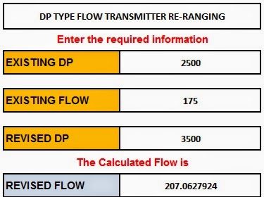
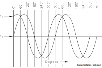
This is mostly known to everyone that a square root Function is required for Orifice Flow Transmitter as the relationship of flow versus pressure is not linear but has a square-root relationship.

Contents
Interface issue between System and field instrument engineerNext Question where should you prefer doing the extraction?Display a Square-rooted output at field But Square-root extraction require in DCS?

But the next question is? where should you do this square-root function?

In Transmitter or DCS or both or none?

Note: we can do this square root function in two ways. one using the physical device called square-root extractor and this is an old method. Second is using the software configuration either in transmitter or in DCS. Here we are discussing the second method.

Interface issue between System and field instrument engineer

The first point of caution is the proper interface between the requisition (field) engineers and system engineers.

Sometimes the engineer purchasing transmitter assumes it will be done in DCS.

While the system engineer assumes it will be done in Transmitter.

And NOBODY does it.

Similarly, the converse is also true.

The Square-root extraction is done at both places, which again is incorrect.

In short, NOBODY doing it

Or EVERYBODY (Field as well DCS) doing it

Should be avoided.

It should be done in one place ONLY.

Next Question where should you prefer doing the extraction?

Well after having a discussion with a few dependable Vendors they suggest it should be done at the system side.

Reason:-  Some Transmitter’s electronic computational capability is not superior as compared to System (DCS/SIS) side.

 So it is advisable to give that task to the System side.

Please note this is just a recommendation as I have done projects where the client preferred having it done in Transmitter while I have also worked on projects where it was done on the System side.

 But if it is not enforced by client you could do it at the system side.

Read: Square-Root Extractor Device

Display a Square-rooted output at field But Square-root extraction require in DCS?

The situation:- Suppose you want square-root extraction to be done in the System side, But the Transmitter in the field has display, so in the field when someone looks at the transmitter then he would not have a calculator to read the transmitter’s output and do the extraction manually.

So “We would need the transmitter to display the square-rooted output in the field as that is what is useful for someone looking at the display in field”

But we want the extraction to be done at the system end.

The solution:- This feature is available with various vendors but it should be properly communicated.

 The following information must be passed on:-

 1. The transmitter (Tx) will be blind or have a display

2. What range Tx should display example:- 0 to 100 lb/hr

3. Clearly indicate: The Extraction is to be done in the Control system side.

 In order to display the “Square rooted output” the transmitter will do it locally just for display but won’t send the Square-root extracted signal to DCS. That task will be done by DCS.

 Thanks for reading !!

 I hope it’s been of value to you.

PS: This is as per the best of my current understanding.

Author: Asad Shaikh

Profile: Linkedin

If you liked this article, then please subscribe to our YouTube Channel for Instrumentation, Electrical, PLC, and SCADA video tutorials.

You can also follow us on Facebook and Twitter to receive daily updates.

Read Next:

  • Integral Flow Orifice Assembly
  • What is an Orifice Flange?
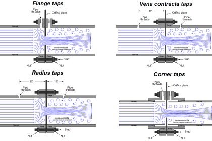
  • Types of Orifice Tappings
  • What are the different Orifice Plates?
  • Turndown ratio of Orifice Plates
Don't Miss Our Updates
Be the first to get exclusive content straight to your email.
We promise not to spam you. You can unsubscribe at any time.
Invalid email address
You've successfully subscribed !

Recommended Articles

Overview of Positive Displacement Flow Meters
Augmented Reality and Virtual Reality in Industrial Automation
What is a Annunciator Panel?
Flow Meter Characteristics
Definitions of Electrical Grounding
PID Simulator Download
Share This Article
Facebook Whatsapp Whatsapp LinkedIn Copy Link
Share
6 Comments
  • franciisco c aragon says:
    October 7, 2019 at 5:05 pm

    Do you Remember how works pneumatic relay? Really I didn’t understand this article.
    Francisco.

    Reply
  • S Bharadwaj Reddy says:
    October 7, 2019 at 6:24 pm

    Here we are discussing the square-root configuration in transmitter or DCS using software programming only.

    Reply
  • Ambrose Ejimaji says:
    November 17, 2019 at 4:35 pm

    Thanks Bharadwaj Reddy for this useful information.
    Pls. I want to know the consequential effect if square root Function is done on both DCS and the transmitter.

    Reply
  • Nagewaran K says:
    September 23, 2021 at 5:59 am

    orifice – dp type flow transmitter .the range is 0 – 3000t/h,dp range – 0 – 7438mmh20.five point Calibration tally with yokogawa DCS but when the transmitter output below 0.4% the reading not tally with DCS.the reading in DCS showing linear value.Above 0.4 % the square root value tally in DCS and Transmitter.
    Note – TX output – linear,display – square root
    DCS – SQ ROOT.
    can you please clarify why?

    Reply
    • Gowtham says:
      September 23, 2021 at 7:35 am

      1. Measure the loop current mA when output is below 0.4%
      2. Connect HART and note-down the mA reading (analog output) in the display
      3. The above two readings must match otherwise you may get some errors

      Reply
    • Sangu says:
      September 23, 2021 at 9:52 am

      Hello, you can also try this,

      Transmitter output — Square root, Transmitter Display — Linear
      DCS — Linear,

      This will solve your problem

      Reply

Leave a Reply Cancel reply

Your email address will not be published. Required fields are marked *

Stay Connected

128.3kFollowersLike
69.1kFollowersFollow
208kSubscribersSubscribe
38kFollowersFollow

Categories

Recent Comments

  • William Snyder on Top Non-PLC Certification Courses for Automation Professionals
  • Kamli on Top Free PLC Software
  • Guifty Shimica on Top Non-PLC Certification Courses for Automation Professionals
  • Guifty Shimica on Top Non-PLC Certification Courses for Automation Professionals

Related Articles

Networked SCADA Architecture

Types of SCADA System Architecture

Most Common Types of Cyber Attacks

20 Most Common Types of Cyber Attacks

Measuring Instruments

Flow Instruments – Selection, Principle & Application

L2F insertion-style flowmeter

Optical Flow Meter Principle

PID Tuner

Free PID Controller Gains Tuning Tool

Flow Switch Working

Flow Switch : What is it? – Applications

4-20mA Loop Power Supply Questions

4-20mA Loop Power Supply Questions and Answers

What is PID Controller

What is PID Controller?

More Articles

Temperature Controller

What is a Temperature Controller? – How to Choose?

Smoke Detection System Questions

Interview Questions on Smoke Detection System

Transistor Voltage Divider Bias

Transistor Voltage Divider Bias

PV Tracking in PID Controllers

What is PV Tracking ?

Intrinsic semiconductors

Introduction to Semiconductor Electronics – Types, Materials

Safety Instrumented System (SIS) Worksheets

Safety Instrumented System (SIS) Worksheets and Documents

Venturi Flow Meter Theory

Basics of Venturi Flow Meter

How is pressure drop calculated through a valve?

How is Pressure Drop Calculated through a Valve ?

Follow US
All rights reserved. Reproduction in whole or in part without written permission is prohibited.
Welcome Back!

Sign in to your account

Username or Email Address
Password

Lost your password?