We discuss about concepts of Sink or Source used in electrical circuits or in PLC wiring. Also we deal with basics of normally open contact or normally closed contact which are used in relay wiring.
Sink or Source
When it comes to mastering the language of electronics, nothing causes more confusion than the “sink” or “source” question. This area causes problems for those trying to sort out machine electronics. When ordering parts, we often find ourselves unable to answer the question “do you need sink or source?”
Questions such as these often confront automation engineers and technicians:
If you replace a sinking input with a sourcing input, does it mean that everything that was “on” will now be “off”, and vice-versa?
Is “sinking with normally closed” the same as “sourcing with normally open”?
If your application call specifically for “sinking” or “sourcing”, does that mean you need pnp or npn or does it not matter?
You will be surprised to find out just how easy it is to understand this concept.
Take a look at the circuit in Figure 1. This is our most basic circuit. Even though it is a simple circuit, we can use this circuit to explain sinking and sourcing.
The circuit in Figure 1 shows a light bulb that is connected to a battery with two wires. DC (direct current) flows from the battery, through the light bulb, and back to the battery.
That is all it takes to light the bulb. Connect positive (+) to one side of the bulb, connect negative (-) to the other side of the bulb, and it turns on. This circuit contains the basic requirements of a digital system: a power source (the battery), a device that is turned on and off (the bulb) and wires to connect them together.
Example Circuit
Now we will add one more feature: suppose you want to turn the light on and off? You need to add a switch (or two?). Here is the big question:
Do you add the switch to wire A or do you add switch to wire B? Or do you add two switches?
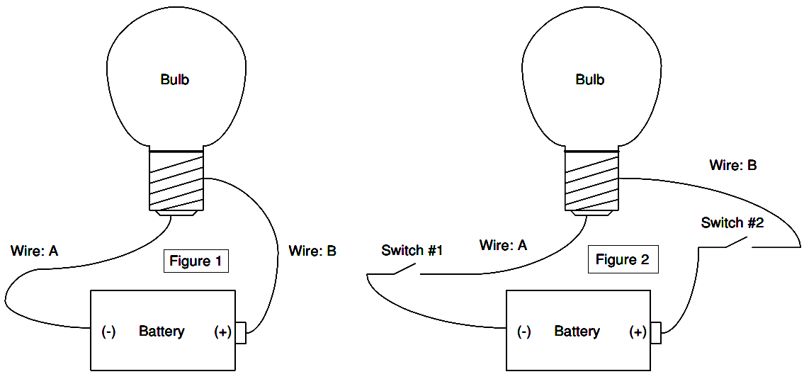
Figure 2 shows two switches installed in the circuit. You probably already know that one switch will do the job. After all, you have been turning lights on and off all your life with just once switch.
So you probably also guessed that it would be foolish to use two switches where one will do the job. But which switch do you choose? Do you install a switch on Wire A as shown in Figure 3; or do you install a switch on Wire B as shown in Figure 4.
Drum roll please… the answer is: it doesn’t make any difference; either switch will work fine! Either switch will break the flow of current through the circuit.
Now here is the part that causes all of the confusion: we need a way to describe using switch 1 vs. switch 2. If you examine Figure 3 you will see that switch 1 is installed on the wire that runs from the negative (-) side of the battery to the light bulb.
You can see in Figure 4 that switch 2 is installed on the wire that runs from the positive (+) side of the battery to the light bulb.
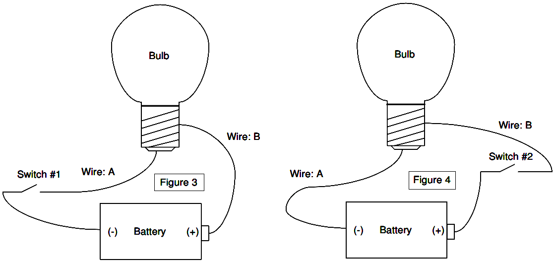
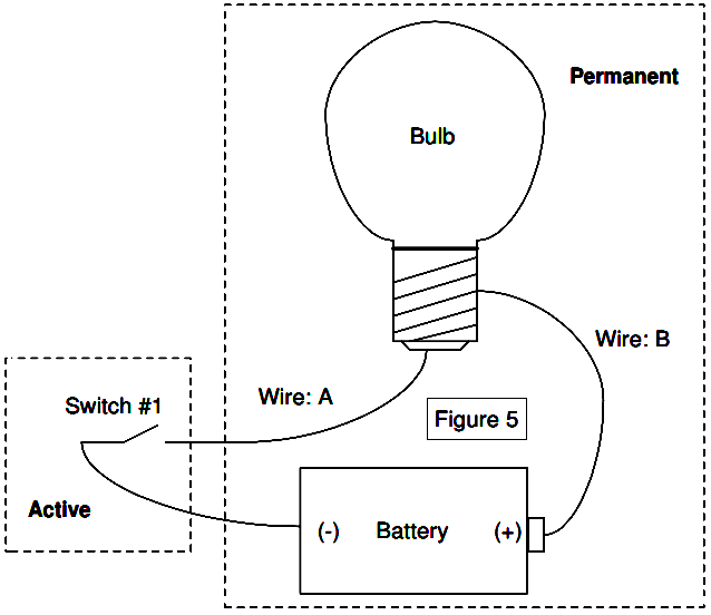
You can see that the final circuit, which contains just one switch (either figure 3 or 4), has two parts: there is an “inactive” part of the system and also an “active” part of the system. Figure 5 shows these two parts. The bulb, the battery and the wire that runs from the (+) side of the battery to the bulb are inactive.
These 3 items sit there all day long and never change. The switch however, is active. It has two states: it can be either ON or OFF. Sometimes people refer to this as OPEN or CLOSED; but those are just different words for the same thing.
Now consider what is happening from the switches point of view in Figure 5. As the switch is opened and closed it takes the negative (-) from the battery and connects or disconnects it with the bulb.
In Figure 4, the switch takes the positive (+) from the battery and connects it to the bulb. Now imagine that you want to tell someone how to wire a circuit. You need to tell them whether they should wire the circuit as shown in Figure 3 or as in Figure 4.
Imagine further that you have lots of people wiring lots of circuits and you need to give these instructions all day long. It’s too much of a mouthful to say “Wire one side of the bulb permanently to positive and install the switch so it connects and disconnects the negative from the battery to the bulb.” Besides, if you say that, you don’t sound very sophisticated.
So someone made up terms to shorten the instructions and help us to sound more sophisticated. And these terms are… SINK and SOURCE. I have no idea why they chose these terms.
They could have used any two terms: “Sink” and “Swim” would have worked just fine; or why not “Source” and “Resource”?
For all we care they can call these two different conditions Moe and Larry. The name is not important, what is important is that when you set up a DC system to turn something on and off, you will switch either the positive or the negative and leave the other permanently wired.
Now, in order to communicate intelligently, all you need to know is… which is Sink and which is Source? Here is something that may surprise you: the terms sink and source are NOT standardized enough across the industry to be relied on.
As incredible as it sounds, when one person refers to what you may call “source” the other person may picture what you would call “sink”. So I recommend that you never use these terms.
Instead, you can review the wiring diagrams, or say something like “switch the negative” or “switch the positive”. Leave the terms “sink” and “source” for those who are so pressed for time that they want to optimize their speech while risking wiring the machine improperly.
So now you know. Next time you here the words “sink” or “source”, just ignore the terminology and focus on what you actually have: are you are switching the positive (+) or the negative (-)? That’s your deciding factor.
Normally Open or Normally Closed
The concept of “normally open” vs. “normally closed” is often confused with sink and source, but these two are not related. will be discussed in next article. Check Here.
If you liked this article, then please subscribe to our YouTube Channel for PLC and SCADA video tutorials.
You can also follow us on Facebook and Twitter to receive daily updates.
Read Next:
- Relay Working Animation
- Failsafe Wiring Practices
- Electrical Schematics
- PLC Ladder Diagrams
- What is a Limit Switch?





Nice & Simple 🙂
Very good example to understand the concept
Perfectly explained. Any one can understand the concept after reading it.Thank you sir.
so finally which is sink?
switch on the negative?