Inst ToolsInst ToolsInst Tools
  • Courses
  • Automation
    • PLC
    • Control System
    • Safety System
    • Communication
    • Fire & Gas System
  • Instrumentation
    • Design
    • Pressure
    • Temperature
    • Flow
    • Level
    • Vibration
    • Analyzer
    • Control Valve
    • Switch
    • Calibration
    • Erection & Commissioning
  • Interview
    • Instrumentation
    • Electrical
    • Electronics
    • Practical
  • Q&A
    • Instrumentation
    • Control System
    • Electrical
    • Electronics
    • Analog Electronics
    • Digital Electronics
    • Power Electronics
    • Microprocessor
  • Request
Search
  • Books
  • Software
  • Projects
  • Process
  • Tools
  • Basics
  • Formula
  • Power Plant
  • Root Cause Analysis
  • Electrical Basics
  • Animation
  • Standards
  • 4-20 mA Course
  • Siemens PLC Course
Reading: Shunt-Wound DC Generators
Share
Font ResizerAa
Inst ToolsInst Tools
Font ResizerAa
  • Courses
  • Design
  • PLC
  • Interview
  • Control System
Search
  • Courses
  • Automation
    • PLC
    • Control System
    • Safety System
    • Communication
    • Fire & Gas System
  • Instrumentation
    • Design
    • Pressure
    • Temperature
    • Flow
    • Level
    • Vibration
    • Analyzer
    • Control Valve
    • Switch
    • Calibration
    • Erection & Commissioning
  • Interview
    • Instrumentation
    • Electrical
    • Electronics
    • Practical
  • Q&A
    • Instrumentation
    • Control System
    • Electrical
    • Electronics
    • Analog Electronics
    • Digital Electronics
    • Power Electronics
    • Microprocessor
  • Request
Follow US
All rights reserved. Reproduction in whole or in part without written permission is prohibited.
Inst Tools > Blog > Electrical Theory > Shunt-Wound DC Generators

Shunt-Wound DC Generators

Last updated: July 28, 2018 12:06 pm
Editorial Staff
Electrical Theory
No Comments
Share
2 Min Read
SHARE

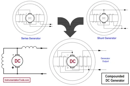
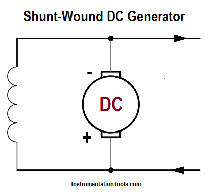
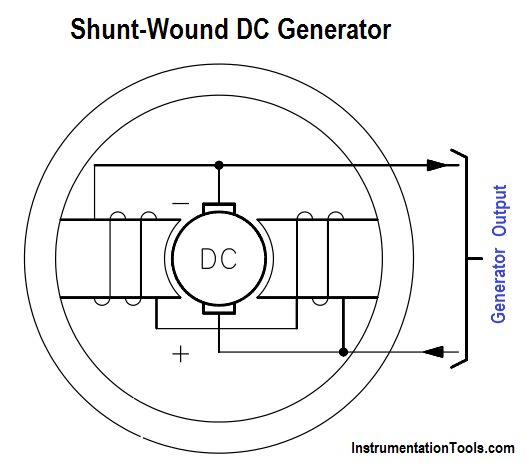
When the field winding of a generator is connected in parallel with the generator armature, the generator is called a shunt-wound generator (Figure 8).

Shunt-Wound DC Generator

Figure 8a : Shunt-Wound DC Generator

The excitation current in a shunt-wound generator is dependent upon the output voltage and the field resistance. Normally, field excitation is maintained between 0.5 and 5 percent of the total current output of the generator.

Shunt-Wound DC Generator Principle

Figure 8 b : Shunt-Wound DC Generator

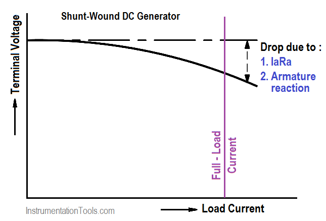
The shunt-wound generator, running at a constant speed under varying load conditions, has a much more stable voltage output than does a series-wound generator. Some change in output voltage does take place. This change is caused by the fact that, as the load current increases, the voltage drop (IaRa) across the armature coil increases, causing output voltage to decrease.

Voltage-vs-Load Current for Shunt-Wound DC Generator

Figure 9 : Output Voltage-vs-Load Current for Shunt-Wound DC Generator

As a result, the current through the field decreases, reducing the magnetic field and causing voltage to decrease even more. If load current is much higher than the design of the generator, the drop in output voltage is severe. For load current within the design range of the generator, the drop in output voltage is minimal (Figure 9).
Don't Miss Our Updates
Be the first to get exclusive content straight to your email.
We promise not to spam you. You can unsubscribe at any time.
Invalid email address
You've successfully subscribed !

Continue Reading

Batteries
Impedance in RLC Circuits
What is a circuit breaker ?
DC Generator
Methods of Producing Voltage (Electricity)
Three Phase Wattmeter
Share This Article
Facebook Whatsapp Whatsapp LinkedIn Copy Link
Share
Leave a Comment

Leave a Reply Cancel reply

Your email address will not be published. Required fields are marked *

Stay Connected

128.3kFollowersLike
69.1kFollowersFollow
210kSubscribersSubscribe
38kFollowersFollow

Categories

Explore More

Transformer Mutual Induction
Three Phase Systems
Losses in AC Generator
Ammeter
Power Triangle
DC Machines Terminology
Starting a Synchronous Motor
Units of Electrical Measurement

Keep Learning

3 Phase Balanced Loads

Power in Balanced 3 Phase Loads

Single Line Diagram

Single Line Diagram

current division Formula for Resistor Circuit

Current Division

Block Diagram

Block Diagram

Types of Batteries

Types of Batteries

Induction Motor Torque

AC Induction Motor Slip

Single Phase Motor Manual Controller

Motor Controllers

Forward Bias

Rectifiers, Forward Bias and Reverse Bias

Learn More

Equal Flow Balance Operation of Parallel Compressors

Types of Surge Control for Parallel Gas Compressors

Oscillators and Signal Generators Objective Questions

Oscillators and Signal Generators Objective Questions

Mixing Process with Valve Control

PLC Mixing Process with Adjustable Timer and Valve Control

Chocked flow

Control Valve Cavitation and Flashing

DC Circuit

Main differences between Sinking and Sourcing Circuits

Pressure Gauge Design

How to Select a Pressure Gauge

What Do You Learn in Software Engineering

What Do You Learn in Software Engineering?

Bipolar Junction Transistors Questions & Answers

Measurement and Instrumentation Objective Questions – Part 1

Menu

  • About
  • Privacy Policy
  • Copyright

Quick Links

  • Learn PLC
  • Helping Hand
  • Part Time Job

YouTube Subscribe

Follow US
All rights reserved. Reproduction in whole or in part without written permission is prohibited.
Welcome Back!

Sign in to your account

Username or Email Address
Password

Lost your password?