Inst ToolsInst ToolsInst Tools
  • Courses
  • Automation
    • PLC
    • Control System
    • Safety System
    • Communication
    • Fire & Gas System
  • Instrumentation
    • Design
    • Pressure
    • Temperature
    • Flow
    • Level
    • Vibration
    • Analyzer
    • Control Valve
    • Switch
    • Calibration
    • Erection & Commissioning
  • Interview
    • Instrumentation
    • Electrical
    • Electronics
    • Practical
  • Q&A
    • Instrumentation
    • Control System
    • Electrical
    • Electronics
    • Analog Electronics
    • Digital Electronics
    • Power Electronics
    • Microprocessor
  • Request
Search
  • Books
  • Software
  • Projects
  • Process
  • Tools
  • Basics
  • Formula
  • Power Plant
  • Root Cause Analysis
  • Electrical Basics
  • Animation
  • Standards
  • 4-20 mA Course
  • Siemens PLC Course
Reading: Series-Wound DC Generators
Share
Font ResizerAa
Inst ToolsInst Tools
Font ResizerAa
  • Courses
  • Design
  • PLC
  • Interview
  • Control System
Search
  • Courses
  • Automation
    • PLC
    • Control System
    • Safety System
    • Communication
    • Fire & Gas System
  • Instrumentation
    • Design
    • Pressure
    • Temperature
    • Flow
    • Level
    • Vibration
    • Analyzer
    • Control Valve
    • Switch
    • Calibration
    • Erection & Commissioning
  • Interview
    • Instrumentation
    • Electrical
    • Electronics
    • Practical
  • Q&A
    • Instrumentation
    • Control System
    • Electrical
    • Electronics
    • Analog Electronics
    • Digital Electronics
    • Power Electronics
    • Microprocessor
  • Request
Follow US
All rights reserved. Reproduction in whole or in part without written permission is prohibited.
Inst Tools > Blog > Electrical Theory > Series-Wound DC Generators

Series-Wound DC Generators

Last updated: July 28, 2018 12:52 pm
Editorial Staff
Electrical Theory
No Comments
Share
2 Min Read
SHARE

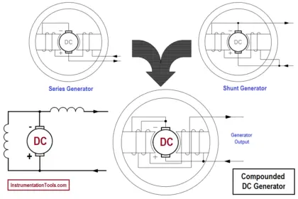
When the field winding of a DC generator is connected in series with the armature, the generator is called a series-wound generator (Figure 10).

Series-Wound DC Generator

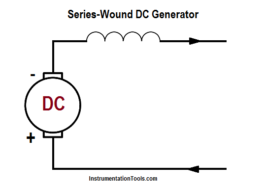
Figure 10a :  Series-Wound DC Generator

The excitation current in a series-wound generator is the same as the current the generator delivers to the load. If the load has a high resistance and only draws a small amount of current, the excitation current is also small. Therefore, the magnetic field of the series field winding is weak, making the generated voltage low.

Series-Wound DC Generator Principle

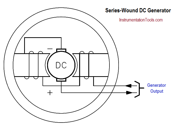
Figure 10b :  Series-Wound DC Generator

Conversely, if the load draws a large current, the excitation current is also high. Therefore, the magnetic field of the series field winding is very strong, and the generated voltage is high.

Output Voltage versus Load Current for Series-Wound DC Generator

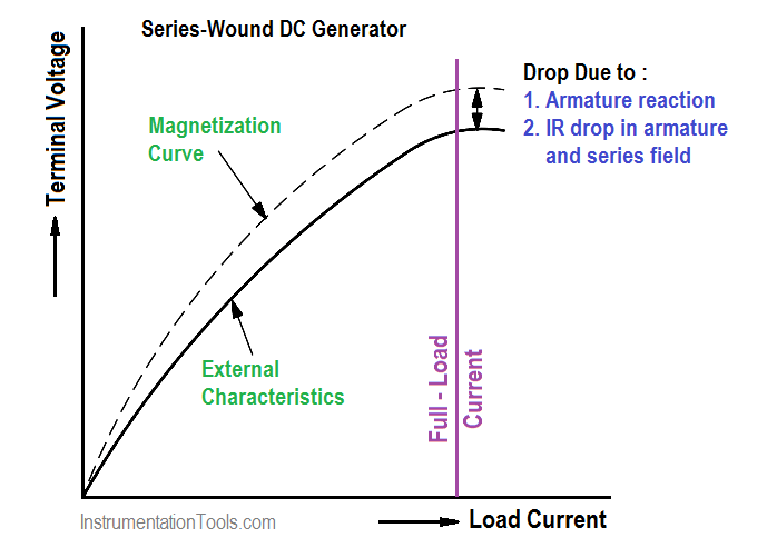
Figure 11 : Output Voltage-vs-Load Current for Series-Wound DC Generator

As you can see in Figure 11, in a series generator, changes in load current drastically affect the generator output voltage. A series generator has poor voltage regulation, and, as a result, series generators are not used for fluctuating loads.

As is the case for the shunt-wound generator, a series-wound generator also exhibits some losses due to the resistance of the windings and armature reaction. These losses cause a lower terminal voltage than that for an ideal magnetization curve.

Don't Miss Our Updates
Be the first to get exclusive content straight to your email.
We promise not to spam you. You can unsubscribe at any time.
Invalid email address
You've successfully subscribed !

Continue Reading

Series Resistance
Current Division
Starting a Synchronous Motor
Shunt-Wound Motor Operation
Types of Capacitors
Calculate Power in Series RC Circuit
Share This Article
Facebook Whatsapp Whatsapp LinkedIn Copy Link
Share
Leave a Comment

Leave a Reply Cancel reply

Your email address will not be published. Required fields are marked *

Stay Connected

128.3kFollowersLike
69.1kFollowersFollow
210kSubscribersSubscribe
38kFollowersFollow

Categories

Explore More

DC Generator Internal Losses
Electrical Wiring Terminology
Voltage Divider
Losses in AC Generator
Conductor, Insulator, Resistor and Current Flow
Capacitance
Battery Terminology
AC Generator Nameplate Ratings

Keep Learning

relationship between resistance, reactance, and impedance

Impedance

Thermoelectricity principle

Methods of Producing Voltage (Electricity)

Electric Short Circuit

Series Short Circuit Faults

Single Line Diagram

Single Line Diagram

Induced EMF

Magnetic Circuits

Power Factor Meter Principle

Power Factor Meter Principle

3-Wire, Three-Phase Delta Wiring System

3-Wire, Three-Phase Delta Wiring System

Three Phase Wattmeter principle

Ampere Hour Meter

Learn More

Porpoising PID Controller

Recognizing a Porpoising PID Controller

level of liquid inside a vessel

Concept of Redundancy in Control Systems

PID Controller Tunning Manually

PID Controller Parameters Tuning Manually

PLC Based Metro Automation Project

PLC based Metro Automation Project

Total Organic Carbon Analyzers Questions and Answers

Total Organic Carbon Analyzers Questions and Answers

Self Actuated Pressure Control Valve Functional Testing

Self Actuated Pressure Control Valve Functional Testing

Mathematical Models of Physical Systems

Differential Equations of Physical Systems & Dynamics of Robotic Mechanisms

DP type Flow Transmitter Calibration

DP type Flow Transmitter Preventive Maintenance and Calibration

Menu

  • About
  • Privacy Policy
  • Copyright

Quick Links

  • Learn PLC
  • Helping Hand
  • Part Time Job

YouTube Subscribe

Follow US
All rights reserved. Reproduction in whole or in part without written permission is prohibited.
Welcome Back!

Sign in to your account

Username or Email Address
Password

Lost your password?