Inst ToolsInst ToolsInst Tools
  • Courses
  • Automation
    • PLC
    • Control System
    • Safety System
    • Communication
    • Fire & Gas System
  • Instrumentation
    • Design
    • Pressure
    • Temperature
    • Flow
    • Level
    • Vibration
    • Analyzer
    • Control Valve
    • Switch
    • Calibration
    • Erection & Commissioning
  • Interview
    • Instrumentation
    • Electrical
    • Electronics
    • Practical
  • Q&A
    • Instrumentation
    • Control System
    • Electrical
    • Electronics
    • Analog Electronics
    • Digital Electronics
    • Power Electronics
    • Microprocessor
  • Request
Search
  • Books
  • Software
  • Projects
  • Process
  • Tools
  • Basics
  • Formula
  • Power Plant
  • Root Cause Analysis
  • Electrical Basics
  • Animation
  • Standards
  • 4-20 mA Course
  • Siemens PLC Course
Reading: Series and Parallel Capacitors
Share
Font ResizerAa
Inst ToolsInst Tools
Font ResizerAa
  • Courses
  • Design
  • PLC
  • Interview
  • Control System
Search
  • Courses
  • Automation
    • PLC
    • Control System
    • Safety System
    • Communication
    • Fire & Gas System
  • Instrumentation
    • Design
    • Pressure
    • Temperature
    • Flow
    • Level
    • Vibration
    • Analyzer
    • Control Valve
    • Switch
    • Calibration
    • Erection & Commissioning
  • Interview
    • Instrumentation
    • Electrical
    • Electronics
    • Practical
  • Q&A
    • Instrumentation
    • Control System
    • Electrical
    • Electronics
    • Analog Electronics
    • Digital Electronics
    • Power Electronics
    • Microprocessor
  • Request
Follow US
All rights reserved. Reproduction in whole or in part without written permission is prohibited.
Inst Tools > Blog > Electrical Theory > Series and Parallel Capacitors

Series and Parallel Capacitors

Last updated: July 26, 2018 4:53 pm
Editorial Staff
Electrical Theory
No Comments
Share
3 Min Read
SHARE

Capacitors in series are combined like resistors in parallel. Capacitors Connected in Series

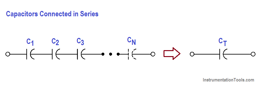
Figure 13 : Capacitors Connected in Series

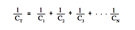
The total capacitance, CT, of capacitors connected in series (Figure 13), is shown in below Equation.

Capacitors Connected in Series Equation

When only two capacitors are in series, Above equation may be simplified as shown below.

Two capacitors Equation

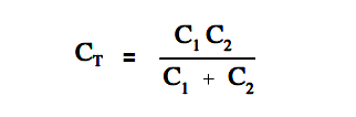
The above Equation is valid when there are only two capacitors in series.

When all the capacitors in series are the same value, the total capacitance can be found by dividing the capacitor’s value by the number of capacitors in series as given in below Equation.
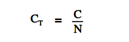
Capacitor in Series Equation

where

C = value of any capacitor in series
N = the number of capacitors in series with the same value.

Capacitors in parallel are combined like resistors in series. When capacitors are connected in parallel (Figure 14), the total capacitance, CT , is the sum of the individual capacitances as given in below Equation.

CT = C1 + C2 + C3 …….. + CN

Capacitors Connected in Parallel

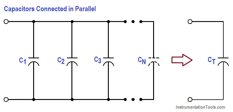
Figure 14 : Capacitors Connected in Parallel

Example 1:

Find the total capacitance of 3µF, 6µF, and 12µF capacitors connected in series (Figure 15).

Find the total capacitance

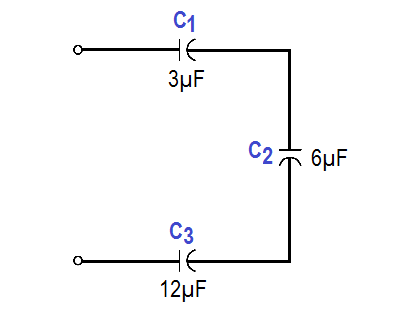
Figure 15  : Example 1 – Capacitors Connected in Series

Capacitors Connected in Series Equation

1/CT = 1/3 + 1/6 + 1/12

CT = 12/7 = 1.7 µF

Example 2:

Find the total capacitance and working voltage of two capacitors in series, when both have a value of 150 µF, 120 V (Figure 16).

two capacitors in series

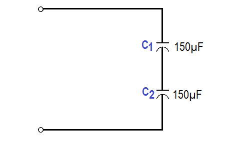
Figure 16 : Example 2 – Capacitors Connected in Series

Capacitor in Series Equation

CT = 150/2 = 75 µF

Total voltage that can be applied across a group of capacitors in series is equal to the sum of the working voltages of the individual capacitors.

working voltage = 120 V + 120 V = 240 volts

Example 3:

Find the total capacitance of three capacitors in parallel, if the values are 15 µF – 50 V, 10 µF-  100 V, and 3 µF – 150 V (Figure 17). What would be the working voltage?

three capacitors in parallel

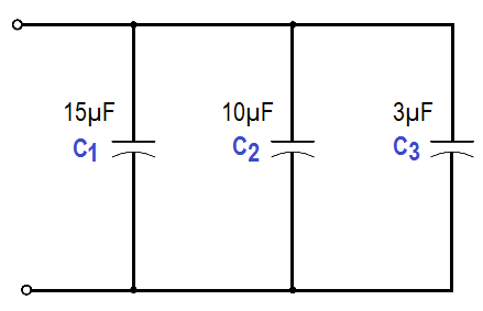
Figure 17 : Example 3 – Capacitors Connected in Parallel

CT = C1 + C2 + C3

CT = 15µF + 10µF + 3µF = 28µF

The working voltage of a group of capacitors in parallel is only as high as the lowest working voltage of an individual capacitor. Therefore, the working voltage of this combination is only 50 volts.

Don't Miss Our Updates
Be the first to get exclusive content straight to your email.
We promise not to spam you. You can unsubscribe at any time.
Invalid email address
You've successfully subscribed !

Continue Reading

Transformer Turns Ratio
Series Resistance
DC Circuit Analysis Node Equations
Capacitor
Single Line Diagram
Voltmeters
Share This Article
Facebook Whatsapp Whatsapp LinkedIn Copy Link
Share
Leave a Comment

Leave a Reply Cancel reply

Your email address will not be published. Required fields are marked *

Stay Connected

128.3kFollowersLike
69.1kFollowersFollow
210kSubscribersSubscribe
38kFollowersFollow

Categories

Explore More

Voltage and Current Phase Relationships in an Inductive Circuit
4-Wire, Three-Phase Delta Wiring System
Power in Balanced 3 Phase Loads
AC Generation Analysis : Effective Values, Phase Angle and Frequency
AC Motor Theory
DC Motor Torque
DC Generator
Wattmeter

Keep Learning

Transformer Operation Under No-Load

Transformer Operation Under No-Load

Generator Action in a Motor

What is Synchroscope ?

Total Resistance in a Parallel Circuit

Resistance in Parallel Circuits

AC to DC Conversion with a Commutator

DC Machines Terminology

Types of Fuses

Electrical System Components and Protection Devices

Capacitive Time Constant for Charging Capacitor

Capacitive Time Constant

Forward Bias

Rectifiers, Forward Bias and Reverse Bias

Ammeter with Shunt

Ammeter

Learn More

UV Visible Spectrometers Questions and Answers

UV Visible Spectrometers Questions and Answers

PLC Count values higher than 999

PLC Count values higher than 999

ORP Measurement

Basics of ORP Measurement

Pilot operated Solenoid Valve Principle

How Pilot operated Solenoid Valve Works ?

Switched Mode Power Supply (SMPS)

How does SMPS Works? – Switched Mode Power Supply

Electrical Conduit Seal

Assembling an Electrical Conduit Seal

Car Lifts

Car Lifts – Choosing the Right One for Your Mechanic Shop

thermocouple Transmitter Formula

Calculate Process Temperature using a Thermocouple

Menu

  • About
  • Privacy Policy
  • Copyright

Quick Links

  • Learn PLC
  • Helping Hand
  • Part Time Job

YouTube Subscribe

Follow US
All rights reserved. Reproduction in whole or in part without written permission is prohibited.
Welcome Back!

Sign in to your account

Username or Email Address
Password

Lost your password?