Before discussing about the Scada systems we have to understand the terminology of the word “SCADA” with respect to olden days and modern era. In the olden days, SCADA systems represent complete hardware, software, and other communication modules.
With the development of PLC and DCS systems, the term “SCADA” specifically using only for the display of the information in the workstation/operator graphics, so SCADA is nothing but a complete programming software unit.
Even some industrial sectors still using the term “SCADA” for representing both hardware and software. In this article, we are discussing the topic with respect to the olden days.
SCADA Systems
SCADA systems are used to control dispersed assets where centralized data acquisition is as important as control. These systems are used in distribution systems such as water distribution and wastewater collection systems, oil and natural gas pipelines, electrical utility transmission and distribution systems, and rail and other public transportation systems.
SCADA systems integrate data acquisition systems with data transmission systems and HMI software to provide a centralized monitoring and control system for numerous process inputs and outputs.
SCADA systems are designed to collect field information, transfer it to a central computer facility, and display the information to the operator graphically or textually, thereby allowing the operator to monitor or control an entire system from a central location in near real-time.
Based on the sophistication and setup of the individual system, control of any individual system, operation, or task can be automatic, or it can be performed by operator commands.
Typical hardware includes a control server placed at a control center, communications equipment (e.g., radio, telephone line, cable, or satellite), and one or more geographically distributed field sites consisting of Remote Terminal Units (RTUs) and/or PLCs, which controls actuators and/or monitors sensors.
The control server stores and processes the information from RTU inputs and outputs, while the RTU or PLC controls the local process. The communications hardware allows the transfer of information and data back and forth between the control server and the RTUs or PLCs.
The software is programmed to tell the system what and when to monitor, what parameter ranges are acceptable, and what response to initiate when parameters change outside acceptable values.
An Intelligent Electronic Device (IED), such as a protective relay, may communicate directly to the control server, or a local RTU may poll the IEDs to collect the data and pass it to the control server.
IEDs provide a direct interface to control and monitor equipment and sensors.
IEDs may be directly polled and controlled by the control server and in most cases have local programming that allows for the IED to act without direct instructions from the control center.
SCADA systems are usually designed to be fault-tolerant systems with significant redundancy built into the system. Redundancy may not be a sufficient countermeasure in the face of malicious attacks.
General configuration of a SCADA system
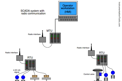
Figure 1 shows the components and general configuration of a SCADA system. The control center houses a control server and the communications routers. Other control center components include the HMI, engineering workstations, and the data historian, which are all connected by a LAN.
The control center collects and logs information gathered by the field sites, displays information to the HMI, and may generate actions based upon detected events. The control center is also responsible for centralized alarming, trend analyses, and reporting.
The field site performs local control of actuators and monitors sensors (Note that sensors and actuators are only shown in Figure 4). Field sites are often equipped with a remote access capability to allow operators to perform remote diagnostics and repairs usually over a separate dial-up modem or WAN connection.
Standard and proprietary communication protocols running over serial and network communications are used to transport information between the control center and field sites using telemetry techniques such as telephone line, cable, fiber, and radiofrequency such as broadcast, microwave, and satellite.
SCADA communication topologies vary among implementations. The various topologies used, including point-to-point, series, series-star, and multi-drop, are shown in Figure 2.
Point-to-point is functionally the simplest type; however, it is expensive because of the individual channels needed for each connection.
In a series configuration, the number of channels used is reduced; however, channel sharing has an impact on the efficiency and complexity of SCADA operations.
Similarly, the series-star and multi-drop configurations’ use of one channel per device results in decreased efficiency and increased system complexity.
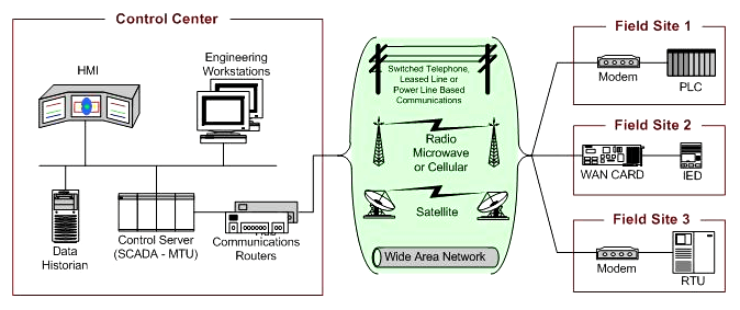
Figure 1. SCADA System General Layout
SCADA Topologies
The four basic topologies Figure 2 can be further augmented using dedicated devices to manage communication exchanges as well as message switching and buffering.
Basic SCADA Topology
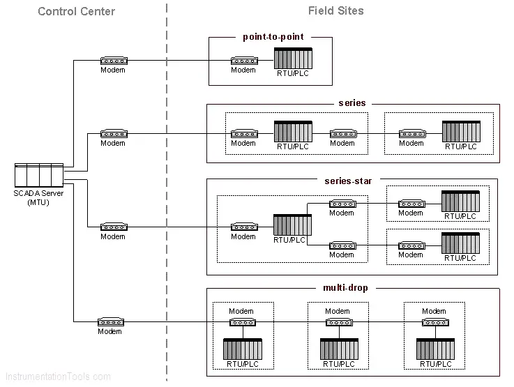
Figure 2. Basic SCADA Communication Topologies
Large SCADA Topology
Large SCADA systems containing hundreds of RTUs often employ a sub-control server to alleviate the burden on the primary server. This type of topology is shown in Figure 3.
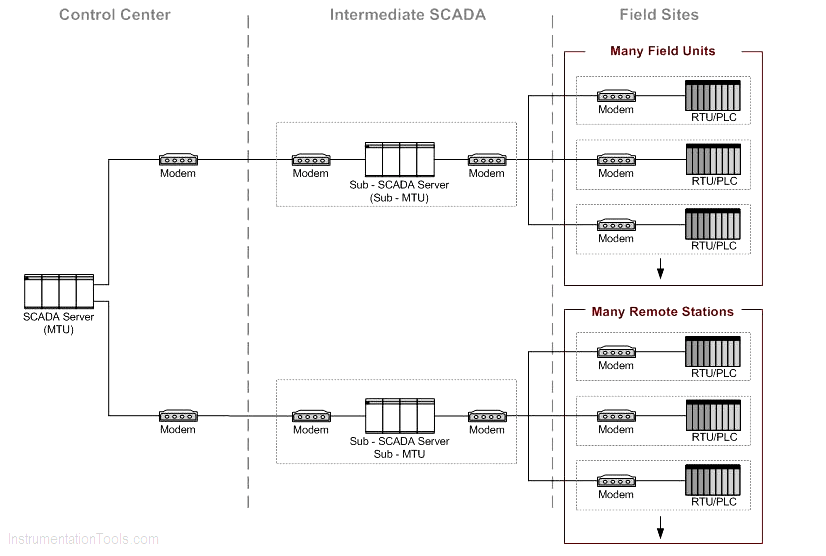
Figure 3. Large SCADA Communication Topology
SCADA System Implementation Example
Distribution Monitoring and Control
Figure 4 shows an example of a SCADA system implementation. This particular SCADA system consists of a primary control center and three field sites.
A second backup control center provides redundancy in the event of a primary control center malfunction.
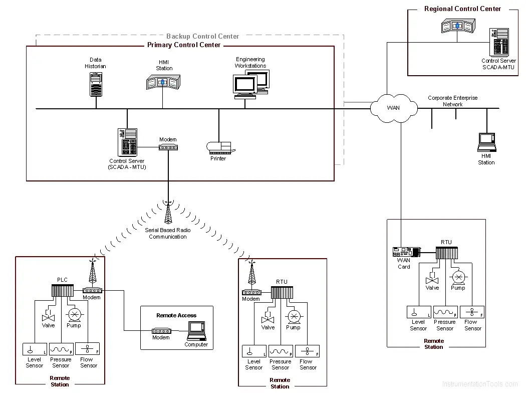
Figure 4. SCADA System Implementation Example (Distribution Monitoring and Control)
Point-to-point connections are used for all control centers to field site communications, with two connections using radio telemetry.
The third field site is local to the control center and uses the WAN for communications. A regional control center resides above the primary control center for a higher level of supervisory control.
The corporate network has access to all control centers through the WAN, and field sites can be accessed remotely for troubleshooting and maintenance operations. The primary control center polls field devices for data at defined intervals (e.g., 5 seconds, 60 seconds) and can send new set points to a field device as required.
In addition to polling and issuing high-level commands, the control server also watches for priority interrupts coming from field site alarm systems.
Rail Monitoring and Control
Figure 5 shows an example of an implementation for rail monitoring and control. This example includes a rail control center that houses the SCADA system and three sections of a rail system.
The SCADA system polls the rail sections for information such as the status of the trains, signal systems, traction electrification systems, and ticket vending machines. This information is also fed to operator consoles at the HMI station within the rail control center.
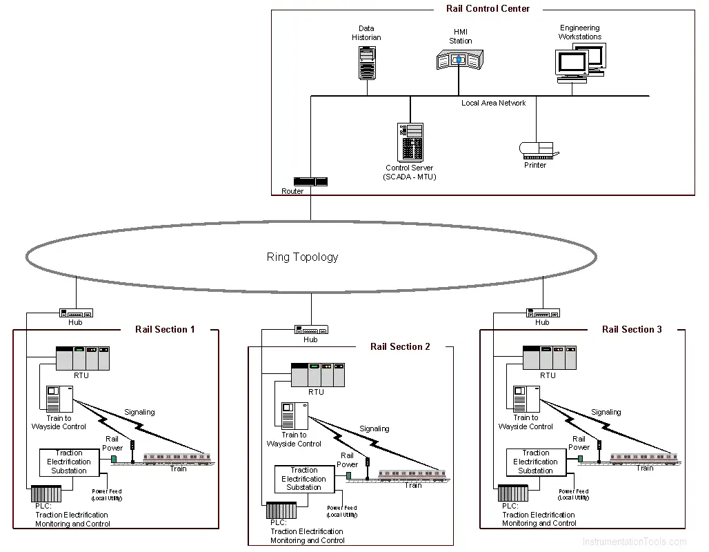
Figure 5. SCADA System Implementation Example (Rail Monitoring and Control)
The SCADA system also monitors operator inputs at the rail control center and disperses high-level operator commands to the rail section components.
In addition, the SCADA system monitors conditions at the individual rail sections and issues command based on these conditions (e.g., stopping a train to prevent it from entering an area that has been determined to be flooded or occupied by another train based on condition monitoring).
Programmable Logic Controller Based Topologies
PLCs are used in both SCADA and DCS systems as the control components of an overall hierarchical system to provide local management of processes through feedback control as described in the sections above.
In the case of SCADA systems, they may provide the same functionality of RTUs. When used in DCS, PLCs are implemented as local controllers within a supervisory control scheme.
In addition to PLC usage in SCADA and DCS, PLCs are also implemented as the primary controller in smaller control system configurations to provide operational control of discrete processes such as automobile assembly lines and power plant soot blower controls.
These topologies differ from SCADA and DCS in that they generally lack a central control server and HMI and, therefore, primarily provide closed-loop control without direct human involvement.
PLCs have a user-programmable memory for storing instructions for the purpose of implementing specific functions such as I/O control, logic, timing, counting, three mode proportional-integral-derivative (PID) control, communication, arithmetic, and data and file processing.
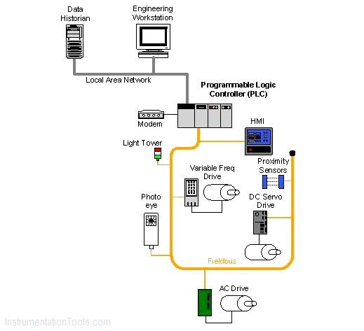
Figure 6. PLC Control System Implementation Example
Figure 6 shows control of a manufacturing process being performed by a PLC over a fieldbus network. The PLC is accessible via a programming interface located on an engineering workstation, and data is stored in a data historian, all connected on a LAN.
Reference: National Institute of Standards and Technology Special Publication 800-82, Revision
If you liked this article, then please subscribe to our YouTube Channel for PLC and SCADA video tutorials.
You can also follow us on Facebook and Twitter to receive daily updates.
Read Next:
- Industrial Control System
- Control System Architecture
- PLC Control System OPC
- Substation SCADA Application
- SCADA Operator Interface