Inst ToolsInst ToolsInst Tools
  • Courses
  • Automation
    • PLC
    • Control System
    • Safety System
    • Communication
    • Fire & Gas System
  • Instrumentation
    • Design
    • Pressure
    • Temperature
    • Flow
    • Level
    • Vibration
    • Analyzer
    • Control Valve
    • Switch
    • Calibration
    • Erection & Commissioning
  • Interview
    • Instrumentation
    • Electrical
    • Electronics
    • Practical
  • Q&A
    • Instrumentation
    • Control System
    • Electrical
    • Electronics
    • Analog Electronics
    • Digital Electronics
    • Power Electronics
    • Microprocessor
  • Request
Search
  • Books
  • Software
  • Projects
  • Process
  • Tools
  • Basics
  • Formula
  • Power Plant
  • Root Cause Analysis
  • Electrical Basics
  • Animation
  • Standards
  • 4-20 mA Course
  • Siemens PLC Course
Reading: Why RTD installed after the Orifice Plate ?
Share
Font ResizerAa
Inst ToolsInst Tools
Font ResizerAa
  • Courses
  • Design
  • PLC
  • Interview
  • Control System
Search
  • Courses
  • Automation
    • PLC
    • Control System
    • Safety System
    • Communication
    • Fire & Gas System
  • Instrumentation
    • Design
    • Pressure
    • Temperature
    • Flow
    • Level
    • Vibration
    • Analyzer
    • Control Valve
    • Switch
    • Calibration
    • Erection & Commissioning
  • Interview
    • Instrumentation
    • Electrical
    • Electronics
    • Practical
  • Q&A
    • Instrumentation
    • Control System
    • Electrical
    • Electronics
    • Analog Electronics
    • Digital Electronics
    • Power Electronics
    • Microprocessor
  • Request
Follow US
All rights reserved. Reproduction in whole or in part without written permission is prohibited.
Inst Tools > Blog > Temperature Measurement > Why RTD installed after the Orifice Plate ?

Why RTD installed after the Orifice Plate ?

Last updated: December 29, 2018 10:41 am
Editorial Staff
Temperature Measurement
2 Comments
Share
1 Min Read
SHARE

Why RTD installed after the Orifice Plate ?

The location of the RTD (thermowell), positioned downstream of the orifice plate so the turbulence it generates will not create additional turbulence at the orifice plate. The American Gas Association (AGA) allows for upstream placement of the thermowell, but only if located at least three feet upstream of a flow conditioner.

A major reason for this is von K´arm´an vortex shedding caused by the gas having to flow around the width of the thermowell. The “street” of vortices shed by the thermowell will cause serious pressure fluctuations at the orifice plate unless mitigated by a flow conditioner, or by locating the thermowell downstream so that the vortices do not reach the orifice.

Also Read : Thermowell Case-Study

Don't Miss Our Updates
Be the first to get exclusive content straight to your email.
We promise not to spam you. You can unsubscribe at any time.
Invalid email address
You've successfully subscribed !

Continue Reading

Thermowell Installation near Critical Equipment
General Specification of Thermowell
Temperature Error of 2-Wire, 3-Wire & 4-Wire RTD
Filled-bulb Temperature Sensors
Calibration of Temperature Sensor with Indicator
RTD Calculator : Calculate Temperature from Resistance
Share This Article
Facebook Whatsapp Whatsapp LinkedIn Copy Link
Share
2 Comments
  • Joseph says:
    May 24, 2018 at 5:24 pm

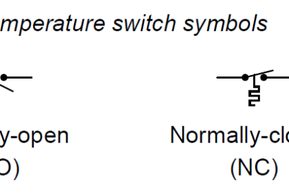
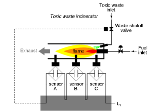
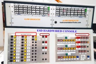
    Please I need an installation hook-up procedure for interface shutdown signals between the Robershall panel and Safety System in control room. We need to install pressure switch and solenoid valve . it is to be configured in such a way that if the there fire in gas plant ESD will be initiated to shutdown the Flowstation and verse versa

    Reply
  • islom says:
    November 10, 2018 at 10:20 pm

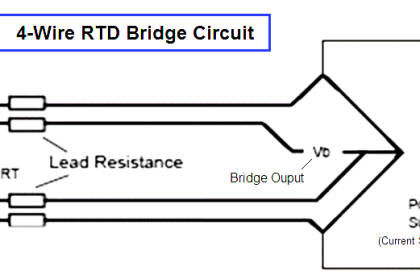
    which conditions can we use fromRTDs? Please give me full informations about this!!!!!!!

    Reply

Leave a Reply Cancel reply

Your email address will not be published. Required fields are marked *

Stay Connected

128.3kFollowersLike
69.1kFollowersFollow
210kSubscribersSubscribe
38kFollowersFollow

Categories

Explore More

Components of RTD
Peltier Effect Theory
RTD Calibration Procedure
Difference between PT100, PT1000, Nickel RTD and Balco RTD
Difference Between RTD, Thermocouple and Thermistor
How to calculate the tolerance of a RTD sensor
Thermocouple Questions and Answers
Thermostat – Types, Working Principle, Advantages, Applications

Keep Learning

RTD Questions & Answers

RTD Questions and Answers

Bimetallic strip thermostat

Mechanical Temperature Measuring Sensors

RTD Testing Methods

RTD Testing Methods in Calibration Laboratory

thermocouple types

What is a Thermocouple ?

Thermocouples Green Rot Effect

Thermocouples Green Rot Effect

RTD with Thermowell

Temperature Sensor Accessories

How to calculate Thermocouple Temperature by measuring the output millivoltage

Insulation of Thermowell

Facts on Thermowell Insulation Thickness

Learn More

RF and RTJ Flange Installed Gasket

Flange Joint Errors shutdowns root cause analyzed and eliminated

How do Electric Motors Work

All About Electric Motors and Universal Motors

S84 - IEC 61511 Standard for Safety Instrumented Systems

S84 / IEC 61511 Standard for Safety Instrumented Systems

Electrical & Electronics Measurements Objective Questions

Electrical & Electronics Measurements Objective Questions – Set 3

Strain gage load cells

Load Cell Healthiness Checks

Voltmeter Calibration

Calibration Procedure of Voltmeter and Ammeter

How a Diode Works Animation

How a Gate Works ?

Complementary Split Range Control

What is Complementary Split Range Control (CSRC)?

Menu

  • About
  • Privacy Policy
  • Copyright

Quick Links

  • Learn PLC
  • Helping Hand
  • Part Time Job

YouTube Subscribe

Follow US
All rights reserved. Reproduction in whole or in part without written permission is prohibited.
Welcome Back!

Sign in to your account

Username or Email Address
Password

Lost your password?