Suppose we have a PLC connected to three process switches as shown in this illustration:
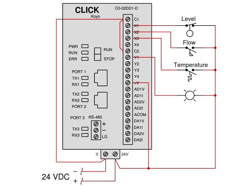
In the above Diagram :
- X1 to X4 : Digital Inputs
- Y1 to Y4 : Digital Outputs
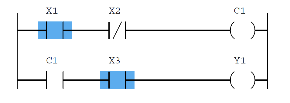
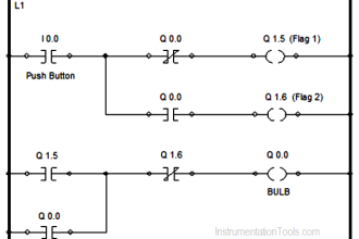
Determine the switch actuation statuses (i.e. low versus high process stimulus) given the “live” display of the ladder logic program shown here:
Also, determine the status of the lamp connected to the PLC’s Y1 output.
Answer :
- Low level and high flow and high temperature.
- The lamp will be de-energized.
Share Your Answer / Comments
Credits : Tony R. Kuphaldt – under CC BY 1.0
For More PLC Questions : CLICK HERE
