Programmable Logic Controller (PLC) Questions and Answers
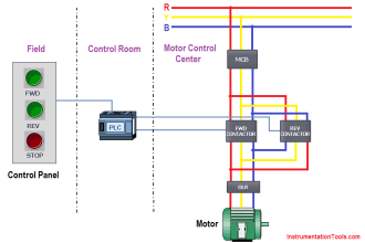
This PLC is being used to start and stop an electric motor, and also to shut it down automatically if any of three “shutdown” conditions occur:
- Excessive vibration
- Overcurrent (overload heater contact)
- High winding temperature
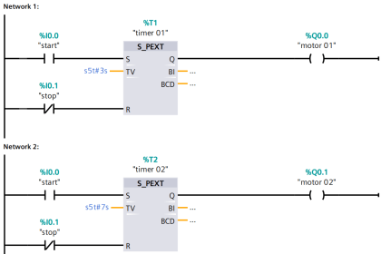
Motor Trip Logic using PLC Programming

The status of each shutdown contact is as follows:
- Vibration contact: closed when okay, opens when vibration becomes excessive
- Overload contact: closed when okay, opens when overloaded
- Temperature contact: open when okay, closes when hot
Draw a PLC ladder-logic program to start and stop this motor.
Be sure to make the program latching so that the operator does not have to hold the Start button to keep the motor running.
Answer:
Do you find any mistakes in the logic? Share with us through comments.

Share Your Answer / Comments
Credits : by Tony R. Kuphaldt – under CC BY 1.0
For More PLC Questions : CLICK HERE
If you liked this article, then please subscribe to our YouTube Channel for PLC and SCADA video tutorials.
You can also follow us on Facebook and Twitter to receive daily updates.


fantastic title
thanks
This is indeed a powerful source of information. I am truly humbled.
Thank you
Maphalla MA
God bless
sorry, X1, X2, X3 should be NC Contacts here.
True…contacts must be closed there…open for TS
good idea
X0,X1,X2,X3, NEED TO NC contact
X1, X2, X3 all is NC Contact.
Stop , vibration, overload should be NC
No they should not. They are NC instruments yes but if you keep as NC in logic motor will not start as they will turn open in the logic
Right