Inst ToolsInst ToolsInst Tools
  • Courses
  • Automation
    • PLC
    • Control System
    • Safety System
    • Communication
    • Fire & Gas System
  • Instrumentation
    • Design
    • Pressure
    • Temperature
    • Flow
    • Level
    • Vibration
    • Analyzer
    • Control Valve
    • Switch
    • Calibration
    • Erection & Commissioning
  • Interview
    • Instrumentation
    • Electrical
    • Electronics
    • Practical
  • Q&A
    • Instrumentation
    • Control System
    • Electrical
    • Electronics
    • Analog Electronics
    • Digital Electronics
    • Power Electronics
    • Microprocessor
Search
  • Books
  • Software
  • Projects
  • Process
  • Tools
  • Basics
  • Formula
  • Power Plant
  • Root Cause Analysis
  • Electrical Basics
  • Animation
  • Standards
  • 4-20 mA Course
  • Siemens PLC Course
Reading: Establish Communication Between Two PLC Via PROFIBUS Protocol
Share
Notification Show More
Font ResizerAa
Inst ToolsInst Tools
Font ResizerAa
  • Courses
  • Design
  • PLC
  • Interview
  • Control System
Search
  • Courses
  • Automation
    • PLC
    • Control System
    • Safety System
    • Communication
    • Fire & Gas System
  • Instrumentation
    • Design
    • Pressure
    • Temperature
    • Flow
    • Level
    • Vibration
    • Analyzer
    • Control Valve
    • Switch
    • Calibration
    • Erection & Commissioning
  • Interview
    • Instrumentation
    • Electrical
    • Electronics
    • Practical
  • Q&A
    • Instrumentation
    • Control System
    • Electrical
    • Electronics
    • Analog Electronics
    • Digital Electronics
    • Power Electronics
    • Microprocessor
Follow US
All rights reserved. Reproduction in whole or in part without written permission is prohibited.
Inst Tools > Blog > PLC Tutorials > Establish Communication Between Two PLC Via PROFIBUS Protocol

Establish Communication Between Two PLC Via PROFIBUS Protocol

Learn how to establish communication between two Siemens PLC via Profibus protocol using Tia portal software.

Last updated: September 28, 2022 2:24 pm
Hussien Ghareb
PLC Tutorials
No Comments
Share
5 Min Read
SHARE

Communication! Do really our Equipment and controllers need to communicate with each other… usually in the small process, there is no need to establish a network between your devices as it could be just one controller.

Contents
What is a PROFIBUS Protocol?Protocol ArchitectureMasterSlaveProfibus Protocol Limitations and CharacteristicsSteps to configure a PROFIBUS network

But in most cases you will find maybe two or three controllers into your plant, to make full control and integration of the process.

These controllers have to see each other they have to speak and transmit data with each other, so one of the most common protocols in the Automation Industry is PROFIBUS, what are its characteristics and application and how to configure a network between two PLCs that is we are going to talk about. Keep focus.

NOTE the primary vendor for this protocol is Siemens.

What is a PROFIBUS Protocol?

PROFIBUS defines the technical features of a serial field bus system, by which distributed digital automation devices, from field to cell level, can be networked together.

It is a multi-master system and so allows the combined operation on one bus of several automation, engineering, and visualization systems with remote peripherals.

Protocol Architecture

This protocol depends on Master-Slave architecture:

Master

Master determines data traffic on the bus and can send messages without an external request if it is in possession of the bus access token.

Masters are also described as active stations.

Slave

The slave is a peripheral device, such as input and output devices, valves, drives, and transmitters. They do not receive a token authorizing bus access.

This means that they can only acknowledge messages received or, at the request of a master, send messages to it. Slaves are described as passive stations.

They only require a small portion of the bus protocol, which means they make implementation possible with little effort.

Profibus Protocol Limitations and Characteristics

OrganizationPROFIBUS & PROFINET International
Physical LayerRS-485
Transmission speedUp to 12Mbit/sec
Address SpaceUp to 126
Telegram244 Bytes
Technology ArchitectureMaster/Slave
Max Cable Length Between two devices100 Up to 1200 Meter That depends on the bit rate used
ConnectivityPA + Others

Steps to configure a PROFIBUS network

Our network consists of:

  • Siemens PLC S7-400 (DP Master) CPU 412-2DP
  • Siemens PLC S7-300 (DP Slave) CPU 312C-2DP
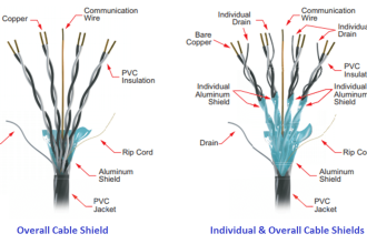
  • PROFIBUS cable (RS485 cable)

Step 1:

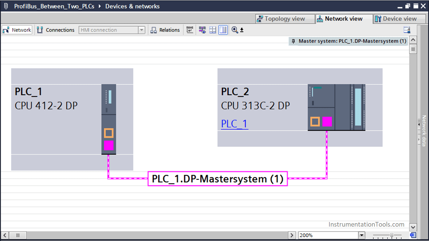
First of all, we will make our Hardware configuration and connect the two PLCs through (DP port)

Connect two PLCs through DP port

Step 2:

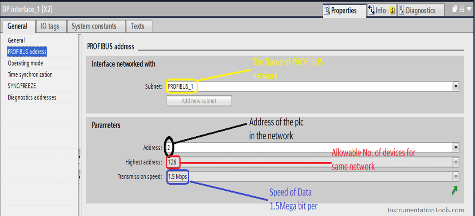
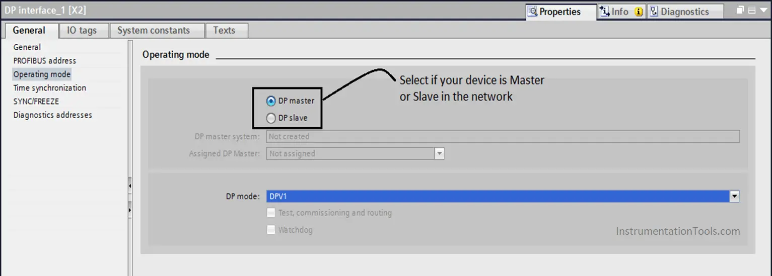
Then we are going to set the DP address and parameters of the PLC by clicking on the PROFIBUS port for (S7-412)

Profibus Address
Profibus Operating Mode

Step 3:

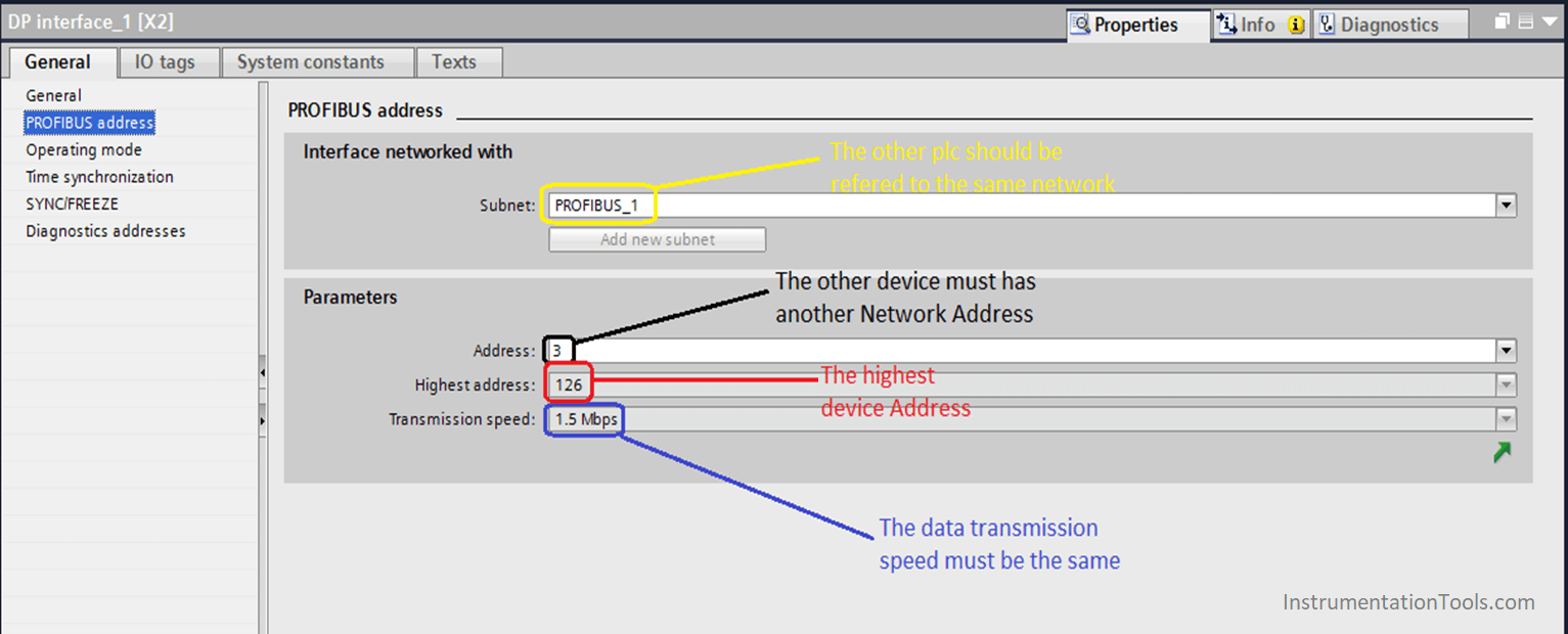
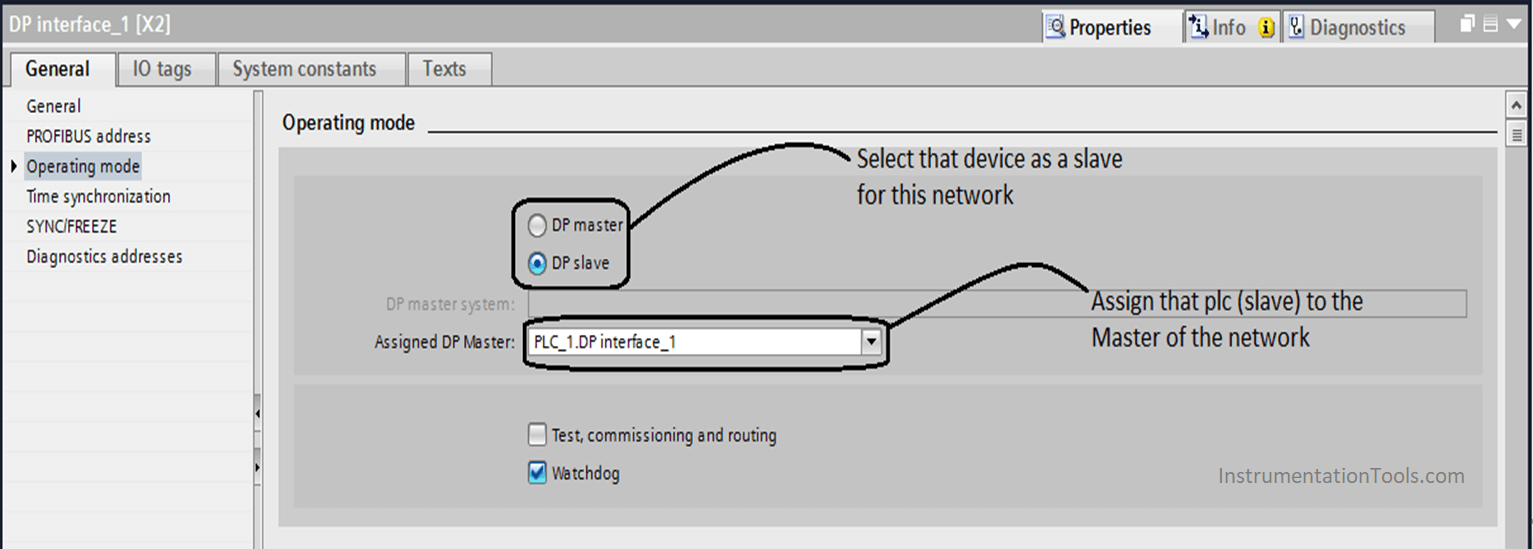
Then we have to set the parameters for the other PLC (S7-312)
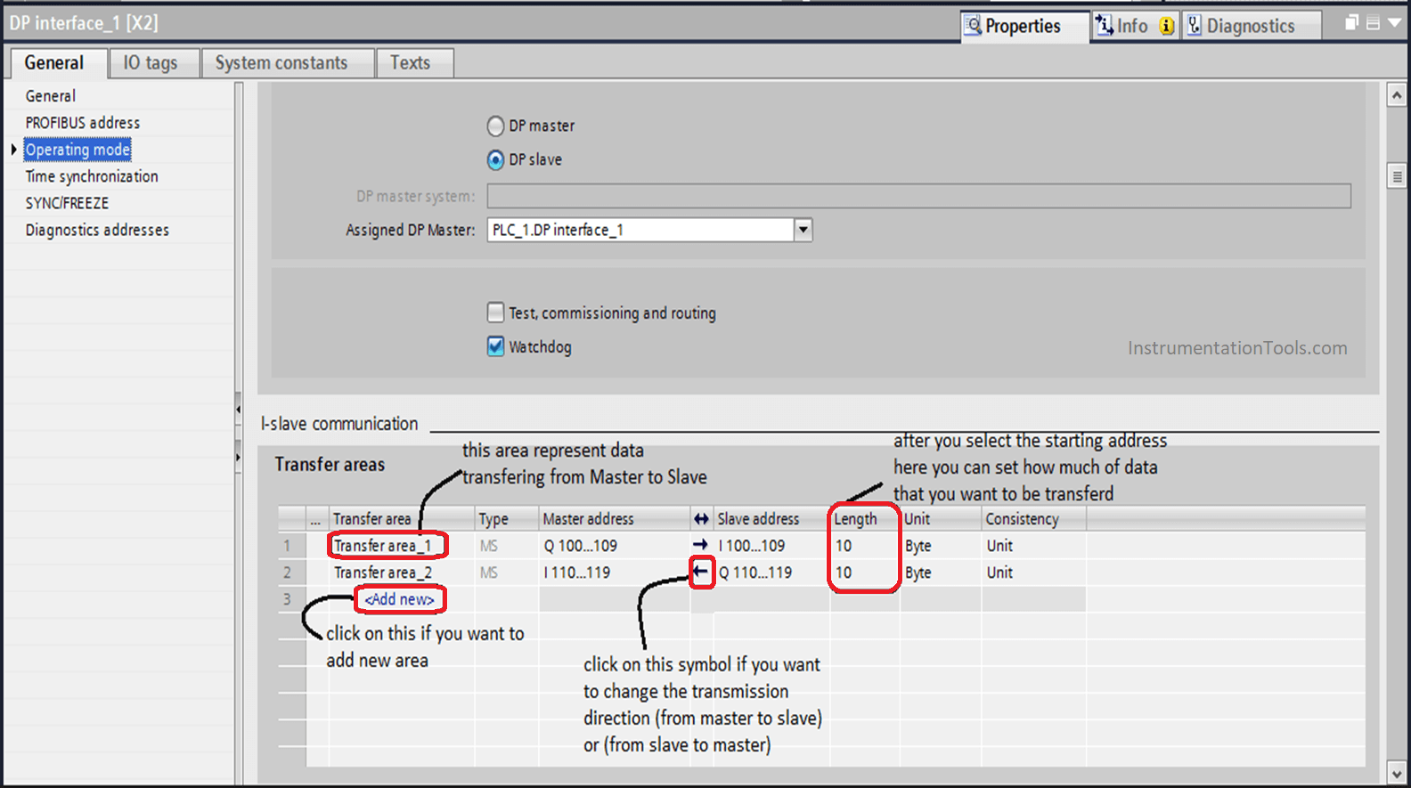
PLC Profibus Configuration
Assign PLC to Master Network

Step 4:

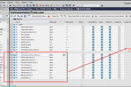
You should be aware that the communication between the two PLCs via PROFIBUS protocol stands on the Input / Output Memory of the devices, for this part you can customize your data addressing for the communication.
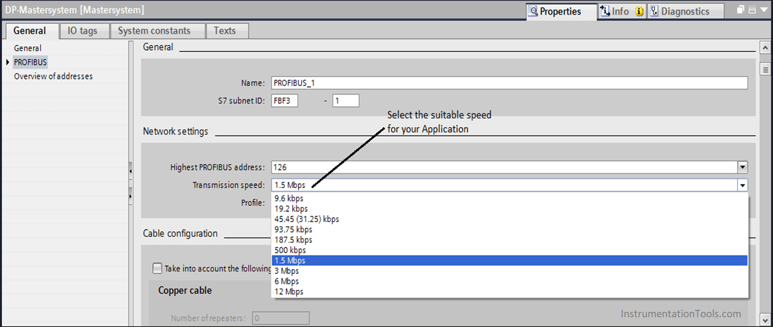
Siemens PLC DP Interface

Step 5:

If you want to change transferring speed you have to click on the PROFIBUS connection between the two PLCs then you can change from here,

Profibus Speed

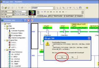
Finally, you can download your program on the PLCs.

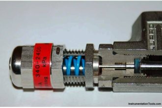
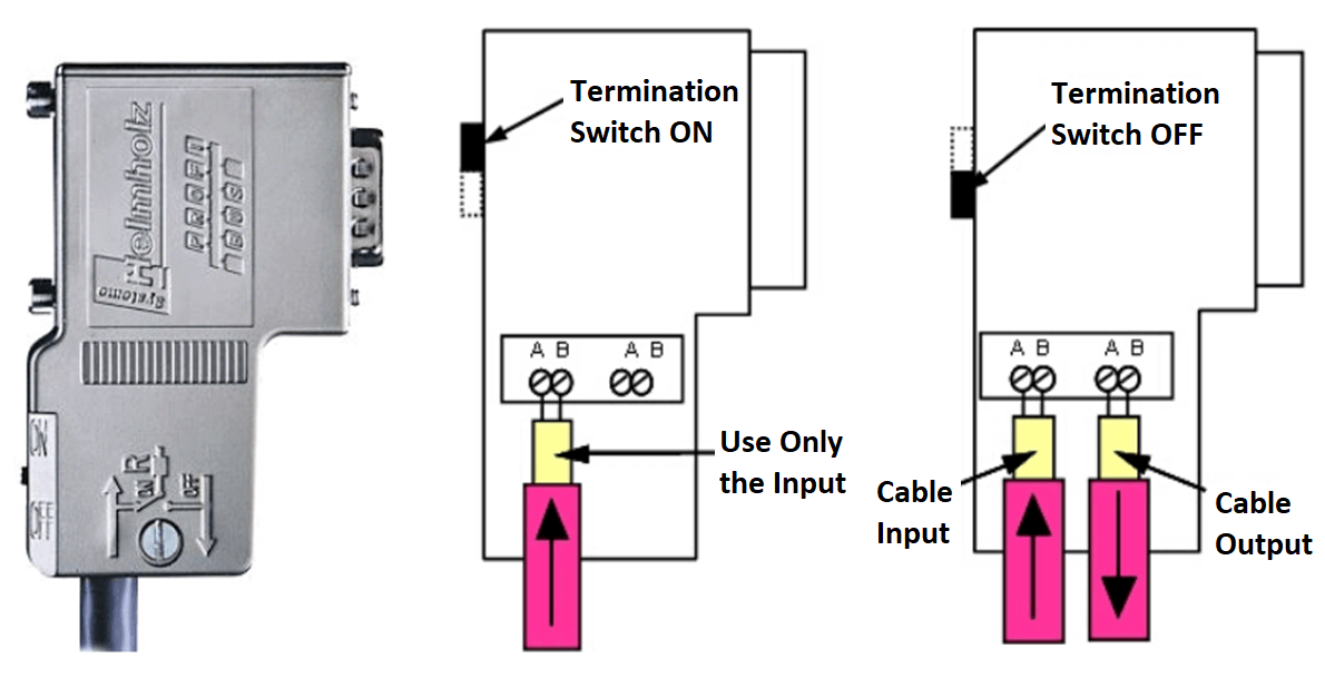
Little Tip in the hardware connection, for the PROFIBUS connector there is a small switch that called Termination resistor.

You have to ensure that it is ON for the two PLCs (as the network consists just of two devices), but in case of that you have a big network that consists of several PROFIBUS devices, you have to make this switch ON for just the first and last devices as they have just Ingoing cable for the connector, and all other devices that they are in between its Termination Resistor should be OFF as there are Ingoing and Outgoing cables for the same connector.

PROFIBUS connector

If you want some Detail information about this Protocol please check this Manual.

If you liked this article, then please subscribe to our YouTube Channel for PLC and SCADA video tutorials.

You can also follow us on Facebook and Twitter to receive daily updates.

Read Next:

  • Types of Limit Switches
  • What is an Electrical Drive?
  • Classifications of PLC
  • PID Simulator Download
  • Timer PLC Ladder Logic
Don't Miss Our Updates
Be the first to get exclusive content straight to your email.
We promise not to spam you. You can unsubscribe at any time.
Invalid email address
You've successfully subscribed !

Continue Reading

Standard Colors in PLC Automation Systems
AENT Module in Rockwell PLC – Remote IO Adapter
PLC Code to Start & Stop Motor and Pump as per Logic
Difference Between Wifi and Industrial Wireless
PLC based Automatic Packaging System
Water Fountain Control Logic – PLC Exercises and Solutions
Share This Article
Facebook Whatsapp Whatsapp LinkedIn Copy Link
Share
Leave a Comment

Leave a Reply Cancel reply

Your email address will not be published. Required fields are marked *

Stay Connected

128.3kFollowersLike
69.1kFollowersFollow
208kSubscribersSubscribe
38kFollowersFollow

Categories

Explore More

Allen Bradley RSLogix 500 PLC Programming
Operator Interface for SCADA System
What is RS Linx? Types of Software in Rockwell Automation
Timer during Motor Direction Change PLC Program
How to Choose a Suitable HMI for Your Application?
PLC Connection between Instrument, Junction Box, Marshalling & System Cabinet
PLC based 4 Way Traffic Light Control System
Basic PLC Exercise on Heater and Cooler for Students

Keep Learning

SCADA System

What is SCADA System?

Star-Delta PLC programming with 1 button

How to Program a Star-Delta System using 1 Button in PLC?

Basic PLC Alarm Programming Example

Basic PLC Alarm Programming Example

Simulator in S7-1200 and S7-1500 PLC

How to Work With Simulator in S7-1200 and S7-1500 PLC?

Automatic bending machine for exhaust pipe

PLC Logic for Automatic Bending Machine for Exhaust Pipe

PLC based Auto Manual Operation of Roll down Shutters

PLC based Auto/Manual Operation of Roll down Shutters in Industry

Instrumentation During the Detail Design Phase

Instrumentation Engineer Activities & Documents – Detail Design Phase

PLC Program for Control Valve Scaling

PLC Program for Control Valve Scaling

Learn More

PLC Controlling a Motor

PLC Motor Control Ladder Logic Programming

Bi-metal Temperature Gauge

Bi-metal Temperature Sensors

Venturi Flow Measurement Principle

Why Flow is Directly Proportional to the Square Root of DP?

Analyzers Questions and Answers

Sodium Analyzer Questions & Answers

Electrical Machines Questions and Answers

Synchronous Machines Power Angle Characteristics Questions

Isometric Projection

Piping and Instrumentation Drawing (P&ID) Tutorials – Part 2

Inverse Time Circuit Breaker

What are Inverse Time and Instantaneous Trip Circuit Breakers?

Automation Engineer Troubleshooting Tips

Best Way to Build Troubleshooting Mindset for Automation Engineer

Follow US
All rights reserved. Reproduction in whole or in part without written permission is prohibited.
Welcome Back!

Sign in to your account

Username or Email Address
Password

Lost your password?