Common

Procedure for Crimping the Connector

Procedure for crimping the connector:

For tubing we used double compression type fitting. Following are the procedure for the tubing:

  1. First select the proper size tube (Like as 6 mm, 10 mm, 12 mm OD). Tube size may depend on your pressure and process services. Material of tube also plays a major role so material also should choose as per your requirement.

Note: There is small difference in inches and mm tubing so choose the correct fitting.

As ¼ “tube and 6 mm tube looks like same.

  1. Inspect the tube. In inspection following point to consider
  2. Check no bending has been occurred. If bending is present in tube then its restrict the flow.
  3. Check the tube path has been cleared. Tube may flush with instrument air to ensure that there is no chocking.
  4. If scratching also present on tube then tubing will not fit the I.D. of the ferrule(s) or the body bore properly and will cause leakage
  5. Cutting the tube at the end with tube cutter. Tube can be cut with hexa but it’s should cut the straight most probably refer the tube cutter.

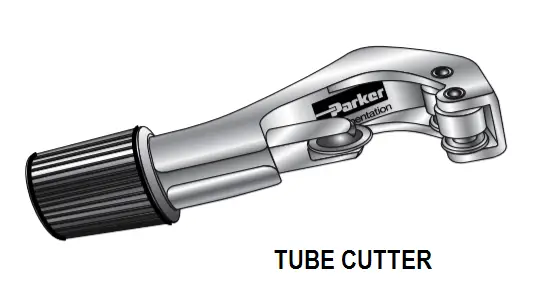
Cutting with Tube cutter: Tube cutter commonly used to cut the tube insert the tube between blade and guider and then move the tuber cutter clockwise and tighten the tube after one cycle then again move cutter one cycle. This is done till the tube cute.

Tube cutter

Cutting with a Hacksaw: – When using a hacksaw to cut off tubing, use a guide to hold the tube to assure the square cut off.

  1. De burring the tube: After the cutting the tube burs are formed which damaging the system. OD burrs can prevent tubing for proper sealing in a connector. ID burs restrict the flow of process. So deburring is removed by flat and round file.
  2. Assembly the Connector: Ferule and connector should be sequenced as shown in figure. If direction is differing then it’s not compress and not fitted proper. Arrange in sequence then tighten the nut on male connector with both ferrules by hand.

Insert the tube in connector and insure that the tube properly fixed in male connector then tight the nut with hand then it’s tightening with slide wrench. Hold the male connector with other wrench and tighten this.

Loosen the nut then checked both ferrule are compressed and no loosen.

Image Credits :  Parker instrument and fittings

Article by :
Ashish Agrawal
You've successfully subscribed !
Share

Recent Articles

  • PLC Tutorials

VFD Simulator Download – Free Yaskawa V1000 Software

VFD simulator download: Master the online tool from the Yaskawa V1000 & programming software for…

2 days ago
  • PLC Tutorials

Conveyor Sorting Machine PLC Program with Calculation Function

The conveyor sorting machine is widely used in the packing industries using the PLC program…

5 days ago
  • PLC Tutorials

Example of Flip-Flop PLC Program for Lamps Application

Learn the example of flip-flop PLC program for lamps application using the ladder logic to…

5 days ago
  • PLC Tutorials

STAR DELTA Programming using PLC Controller

In this article, you will learn the STAR DELTA programming using PLC controller to start…

6 days ago
  • Instrumentation Design

Single and Three Phase Immersion Electrical Heaters Wiring Circuits

Lube oil consoles of rotary equipment packages in industrial process plants are usually equipped with…

3 days ago
  • Instrumentation Design

Immersion Heaters in Lube Oil Consoles

Rotating equipment packages such as pumps, compressors, turbines need the lube oil consoles for their…

5 days ago