Pressure Transmitters Purged impulse lines
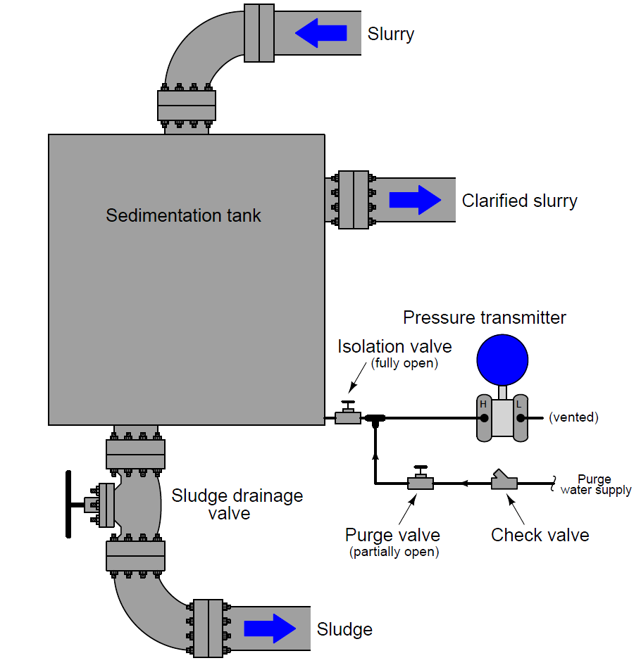
Another method for isolating a pressure instrument from direct contact with process fluid, particularly when the impulse line is prone to plugging, is purging the line with a continuous flow of clean fluid. Consider this example, where pressure is measured at the bottom of a sedimentation vessel:
In this system, a continuous flow of clean water enters through a pressure-dropping “purge valve” and flows through the impulse line, keeping it clear of sediment while still allowing the pressure instrument to sense pressure at the bottom of the vessel.
A check valve guards against reverse flow through the purge line, in case process fluid pressure ever exceeds purge supply pressure. The continuous water purge maintains clean impulse tubing, and ensures the pressure transmitter never contacts process fluid directly.
A very important element of any purge system is a restriction between the purge supply and the connection with the process and pressure-sensing device.
It is important that the pressure-sensing instrument senses the pressure of the process fluid and not the (higher) pressure of the purge fluid supply.
In the example shown, the purge valve fulfills the role of this restriction, which is why it must be left in a partially-open condition, rather than fully-open.
If this purge restriction is not restrictive enough, the purge fluid flow rate will be too great, resulting in a dynamic pressure drop developed across the length of the impulse line.
This pressure drop will add to the pressure of the process fluid inside the vessel, creating a positive pressure measurement error at the instrument (i.e. the instrument will register more pressure than there actually is in the vessel).
The purge restriction should be set to allow just enough purge fluid flow to guard against plugging, and no more.
Purged systems are very useful, but a few requirements are necessary in order to ensure accurate and reliable operation:
- The purge fluid supply must be reliable: if the flow stops for any reason, the impulse line may plug!
- The purge fluid supply pressure must exceed the process pressure at all times, or else process fluid will flow backward into the impulse line!
- The purge fluid flow must be maintained at a low rate, to avoid pressure measurement errors.
- The purge fluid should be introduced into the impulse line as close to the process connection as possible, to minimize errors due to the purge flow rate through long lengths of tubing.
- The purge fluid must not adversely react with the process.
- The purge fluid must not contaminate the process.
- The purge fluid must be reasonable in cost, since it will be continuously consumed over time.
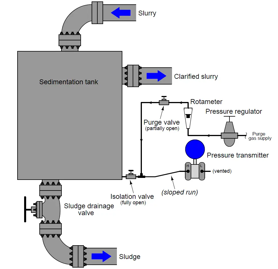
A useful accessory to include in any purge system is a visual flow indicator such as a rotameter.
Such an indicator is useful for manual adjustment of purge flow rate, and also as a troubleshooting aid, to indicate if anything happens to halt the purge flow.
In the previous example, the purge fluid was clean water. Many options exist for purge fluids other than water, though. Gases such as air, nitrogen, or carbon dioxide are often used in purged systems, for both gas and liquid process applications.
An illustration of a gas-purged pressure measurement system is shown here:
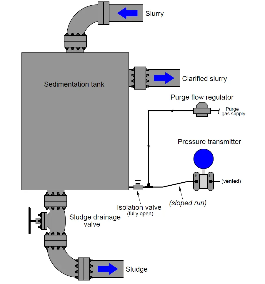
An alternative to the pressure regulator, rotameter, and purge valve is a self-contained unit called a purge flow regulator which automatically adjusts to maintain a constant flow rate of purge gas into the purged impulse line:
It should be noted that liquid-purged impulse lines – just like filled lines and diaphragm-isolated lines – will generate hydrostatic pressure with vertical height. This is not a problem with gas-purged lines.
Credits : Tony R. Kuphaldt – Creative Commons Attribution 4.0 License
