Inst ToolsInst ToolsInst Tools
  • Courses
  • Automation
    • PLC
    • Control System
    • Safety System
    • Communication
    • Fire & Gas System
  • Instrumentation
    • Design
    • Pressure
    • Temperature
    • Flow
    • Level
    • Vibration
    • Analyzer
    • Control Valve
    • Switch
    • Calibration
    • Erection & Commissioning
  • Interview
    • Instrumentation
    • Electrical
    • Electronics
    • Practical
  • Q&A
    • Instrumentation
    • Control System
    • Electrical
    • Electronics
    • Analog Electronics
    • Digital Electronics
    • Power Electronics
    • Microprocessor
  • Request
Search
  • Books
  • Software
  • Projects
  • Process
  • Tools
  • Basics
  • Formula
  • Power Plant
  • Root Cause Analysis
  • Electrical Basics
  • Animation
  • Standards
  • 4-20 mA Course
  • Siemens PLC Course
Reading: Pressure Switch Calibration Procedure
Share
Font ResizerAa
Inst ToolsInst Tools
Font ResizerAa
  • Courses
  • Design
  • PLC
  • Interview
  • Control System
Search
  • Courses
  • Automation
    • PLC
    • Control System
    • Safety System
    • Communication
    • Fire & Gas System
  • Instrumentation
    • Design
    • Pressure
    • Temperature
    • Flow
    • Level
    • Vibration
    • Analyzer
    • Control Valve
    • Switch
    • Calibration
    • Erection & Commissioning
  • Interview
    • Instrumentation
    • Electrical
    • Electronics
    • Practical
  • Q&A
    • Instrumentation
    • Control System
    • Electrical
    • Electronics
    • Analog Electronics
    • Digital Electronics
    • Power Electronics
    • Microprocessor
  • Request
Follow US
All rights reserved. Reproduction in whole or in part without written permission is prohibited.
Inst Tools > Blog > Calibration > Pressure Switch Calibration Procedure

Pressure Switch Calibration Procedure

Last updated: October 21, 2019 4:13 pm
Editorial Staff
Calibration Pressure Measurement
13 Comments
Share
5 Min Read
SHARE

Pressure switches are commonly used in the process industry for a wide range of applications. A pressure switch is a form of sensor that closes or opens an electrical contact when a certain pressure has been obtained either through a pressure rise or a pressure drop.

Contents
Pressure Switch CalibrationCalibration or Verifying a Pressure SwitchRequired Tools:Calibration Procedure :

Pressure switches are used to monitor, control, or provide a caution or warning for a pressure related process. The repeatability, accuracy, and functionality of a pressure switch often tie directly into the safety or efficiency of a process and thus it becomes important that pressure switches are verified and calibrated to ensure their proper function in the process.

Pressure Switch Calibration

There are several terms that describe the function of a switch which need to be understood when testing a pressure switch:

Set point:

The pressure which the switch will change state.

 Normal State:

The state of the switch when at barometric pressure or ideal state.

Depends on Pressure switch type.(typically it would be either OPEN or CLOSED).

Reset:

The pressure at which the switch resets back to the normal state.

Tolerance:

The allowable variation from the set point pressure.

Repeatability:

The closeness of agreement between the results of consecutive measurements.

Dead Band:

The pressure difference between the change-of-states.

(i.e. OPEN to CLOSE or CLOSE to OPEN).

Trip Type:

This is the direction to which the change-of state should happen.

If the trip type is low, this means the change-of-state happens when the pressure is falling.

If the trip type is high, this means the change-of-state happens when the pressure is rising.

Calibration or Verifying a Pressure Switch

Pressure Switch Calibration Procedure

Before implementing the steps, you need to confirm the setpoint and the dead-band of the Pressure switch. In addition, The pressure switch must be depressurized and isolated.

Consider our Pressure Switch is a normally open switch, so we will need to test when the switch changes between open to close. Next, we’ll test the reset pressure (from closed to open) and lastly, repeat the test at least once to determine repeatability.

Required Tools:

  1. we must use a pressure calibrator or Multimeter (DMM) to determine the current state of the switch.
  2. we need to have a pressure generation device (preferably a hand pump ).
  3. we will need a way to measure the true pressure using a pressure calibrator or Pressure gauge.

Calibration Procedure :

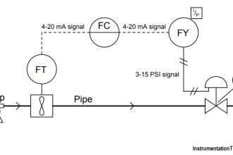
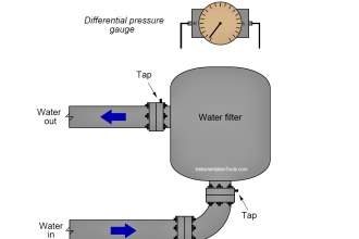
  1. First we connect the pressure gauge and Pressure switch to the hand pump as shown in above figure.
  2. Then we need to measure the present status (NO/NC) of electrical output of the switch with the multimeter.Put multimeter in Continuity mode.
  3. Note: Here in this example our pressure switch considered is Normally open type. So when you connect the multimeter before calibration we have default Normally Open (NO) signal as output.
  4. With our connections complete, we are ready to perform the calibration. We do this by increasing pressure until we detect a change in the switch.
  5. Now increase the pressure with the help of hand pump.
  6. When we see the switch change state from open to close, we record the result.
  7. Next, we decrease the pressure till we see the switch reset (change from close to open) and record the results.
  8. Also record the dead band.
  9. Lastly, we would repeat this test at least once to determine repeatability. The difference between set point and rest pressures is the dead
    band.The dead band must be within the range. The deadband & setpoint of pressure switch available on nameplate of pressure switch.
  10. For Normally closed Pressure switch calibration also follows the same above mentioned procedure. But the default status of Normally closed type Pressure switch will have N.C. signal as output. When testing with increasing pressure the output state changes from N.C. to N.O and while on decreasing pressure the output state changes from N.O. to N.C. Remaining all steps are same. Thats it. very simple.
Don't Miss Our Updates
Be the first to get exclusive content straight to your email.
We promise not to spam you. You can unsubscribe at any time.
Invalid email address
You've successfully subscribed !

Continue Reading

Instrument Protection Methods: Seals
Differential Pressure Transmitter Calibration Procedure
Methods of Measurement
Hierarchy of Calibration Organizations
What is a Dry Block? – Parts of the Temperature Calibrator
Calibration and Troubleshooting of Oxygen Analyzer
Share This Article
Facebook Whatsapp Whatsapp LinkedIn Copy Link
Share
13 Comments
  • Toubro says:
    September 24, 2015 at 11:05 am

    Thanks for sharing with us. It clearly explained pressure switch calibration and its working.

    Reply
  • mayur says:
    October 7, 2015 at 1:11 pm

    Its a superb website..pls make an app for windos……and make videos free download..

    Reply
    • S Bharadwaj Reddy says:
      October 8, 2015 at 2:36 pm

      Noted.

      Reply
  • Desmond says:
    November 20, 2015 at 7:41 am

    Thanks. It was clearly noted and well understood.

    Reply
  • khurshid alam says:
    November 23, 2015 at 1:57 pm

    Sir, this is very useful site. Plz provide calibration videos.

    Reply
  • Ramakrishnan. says:
    December 7, 2015 at 7:27 am

    fantastic info!

    Reply
  • Riyanto says:
    December 8, 2015 at 4:09 am

    I’m so often use this web as a reference works…thank’s sir for accessing free your web.

    Reply
  • manikandan says:
    February 21, 2016 at 5:56 pm

    I really like this all, its is very useful my carrier, thank u so much…

    Reply
  • Suresh says:
    July 24, 2016 at 12:43 pm

    Sir can u explain pressure switch calibration procedures raising and falling conditions while we r doing calibration…..

    Reply
  • azar says:
    August 8, 2016 at 12:13 pm

    thank u sir, its easy to simple way clearly you mentioned procedure

    Reply
  • azar says:
    August 8, 2016 at 12:14 pm

    Pls sent pressure transmitter calibration procedure sir

    Reply
  • ricado says:
    October 26, 2016 at 1:16 pm

    thanks u for this info. u guys are good. thanx

    Reply
  • WonKi Kim says:
    June 29, 2017 at 5:45 pm

    thanks a lot , I really appreciated.

    Reply

Leave a Reply Cancel reply

Your email address will not be published. Required fields are marked *

Stay Connected

128.3kFollowersLike
69.1kFollowersFollow
210kSubscribersSubscribe
38kFollowersFollow

Categories

Explore More

Inclined-limb Manometer Principle
Pressure Gauges : Common Causes for Failures and Their Effective Solutions
How-to do Control Valve Calibration?
Pressure Gauge Water Traps and Pigtail Siphons
Portable Gas Detectors Calibration Procedure
Pneumatic Pressure Transmitters Principle
Impulse Line Pressure Testing Procedure
Hydrogen Sulfide Gas Detector Calibration Procedure

Keep Learning

Why are Impulse Lines often Installed in a Sloping Manner (Angle)

Why are Impulse Lines often Installed in a Sloping Manner?

Top 30 Interview Questions on Pressure Measuring Devices

Top 30 Interview Questions on Pressure Measuring Devices

piping for a Different pressure flow transmitter

Impulse Piping standards for Field instruments

Pressure Gauge Problems

Pressure Gauge Problems

Pressure Gauge Datasheet Preparation

How to Prepare Pressure Gauge Datasheet ?

Pressure Gauges with Diaphragm Sensor Principle

Pressure Gauges with Diaphragm Sensor Principle

Metal Foil Strain Gauge Principle

Metal Foil Strain Gauge Principle

Difference between Accuracy, Tolerance, Uncertainty, and Error

Difference between Accuracy, Tolerance, Uncertainty, and Error

Learn More

How to Use Symbol Factory Software for Graphic Design in HMI or SCADA

How to Use Symbol Factory Software for Graphic Design in HMI or SCADA?

valve trim characteristics

Control Valve Trim Characteristics

Density-Measurement-using-DP-Transmitter-for-Closed-Tank-Wet-leg

Density Measurement using DP Transmitter for closed tank with wet leg

Conductivity measurement

Conductivity Measurement

Siemens Process Mode

Test and Process Modes in Siemens PLC

DP transmitter Elevated 10 Feet above the Vessel

DP transmitter Elevated 10 Feet above the Vessel

Vortex Flow GIF

Working Principle of Vortex Flow Meter

Functional Safety Exam Questions & Answers

Functional Safety Questions & Answers

Menu

  • About
  • Privacy Policy
  • Copyright

Quick Links

  • Learn PLC
  • Helping Hand
  • Part Time Job

YouTube Subscribe

Follow US
All rights reserved. Reproduction in whole or in part without written permission is prohibited.
Welcome Back!

Sign in to your account

Username or Email Address
Password

Lost your password?