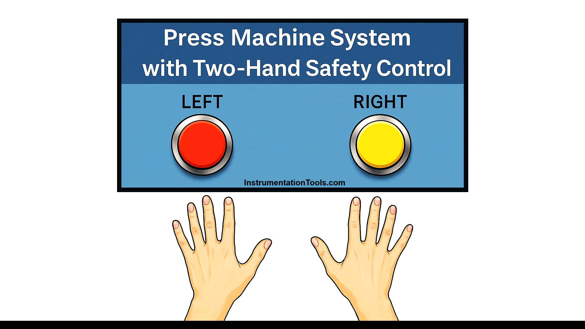
This article discusses the Press Machine System equipped with a Two-Hand Safety Control using Siemens PLC programming. The system is designed so that the press machine can only be operated when the operator uses both hands simultaneously through a two-hand control system. The primary objective of this system is to enhance workplace safety by reducing the risk of injuries caused by negligence or operational accidents.
Program Objective
System Initialization:
- Standby Mode: The System starts operation in standby mode.
- Machine Activation: The press machine can only be activated if both safety buttons, Right and Left, are pressed simultaneously.
Operating Logic:
- Simultaneous Activation: Both safety buttons must be pressed within the specified time frame.
- Inactive Condition: If only one button is pressed, the machine will not operate.
- Operation Duration: Once both buttons are pressed, the Press Machine will operate for 4 seconds.
- Return to Standby Mode: After the operation cycle is completed, the machine will automatically return to standby mode.
Siemens PLC Programming
Mapping Details
| S.No. | Comment | Input (I) | Output (Q) | Memory Bit | Memory Word | Timers |
|---|---|---|---|---|---|---|
| 1 | PB_START | I0.0 | ||||
| 2 | PB_STOP | I0.1 | ||||
| 3 | PB_RIGHT_HAND | I0.2 | ||||
| 4 | PB_LEFT_HAND | I0.3 | ||||
| 5 | RESET_BUTTON | I0.4 | ||||
| 6 | PRESS | Q0.0 | ||||
| 7 | SYSTEM_ON | M4.0 | ||||
| 8 | PRESS_COMMAND | M4.1 | ||||
| 9 | IR1_RIGHT_HAND | M4.2 | ||||
| 10 | IR1_LEFT_HAND | M4.3 | ||||
| 11 | IR2_RIGHT_HAND | M4.4 | ||||
| 12 | IR2_LEFT_HAND | M4.5 | ||||
| 13 | IR_TIMER | M4.6 | ||||
| 14 | TEMP_BIT1 | MW0 | ||||
| 15 | TEMP_BIT2 | MW1 | ||||
| 16 | COUNTER | MW2 | ||||
| 17 | TIMER_INTERLOCK | DB1 |
Press Machine Safety Control
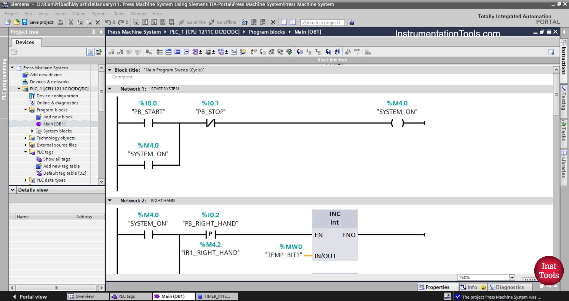
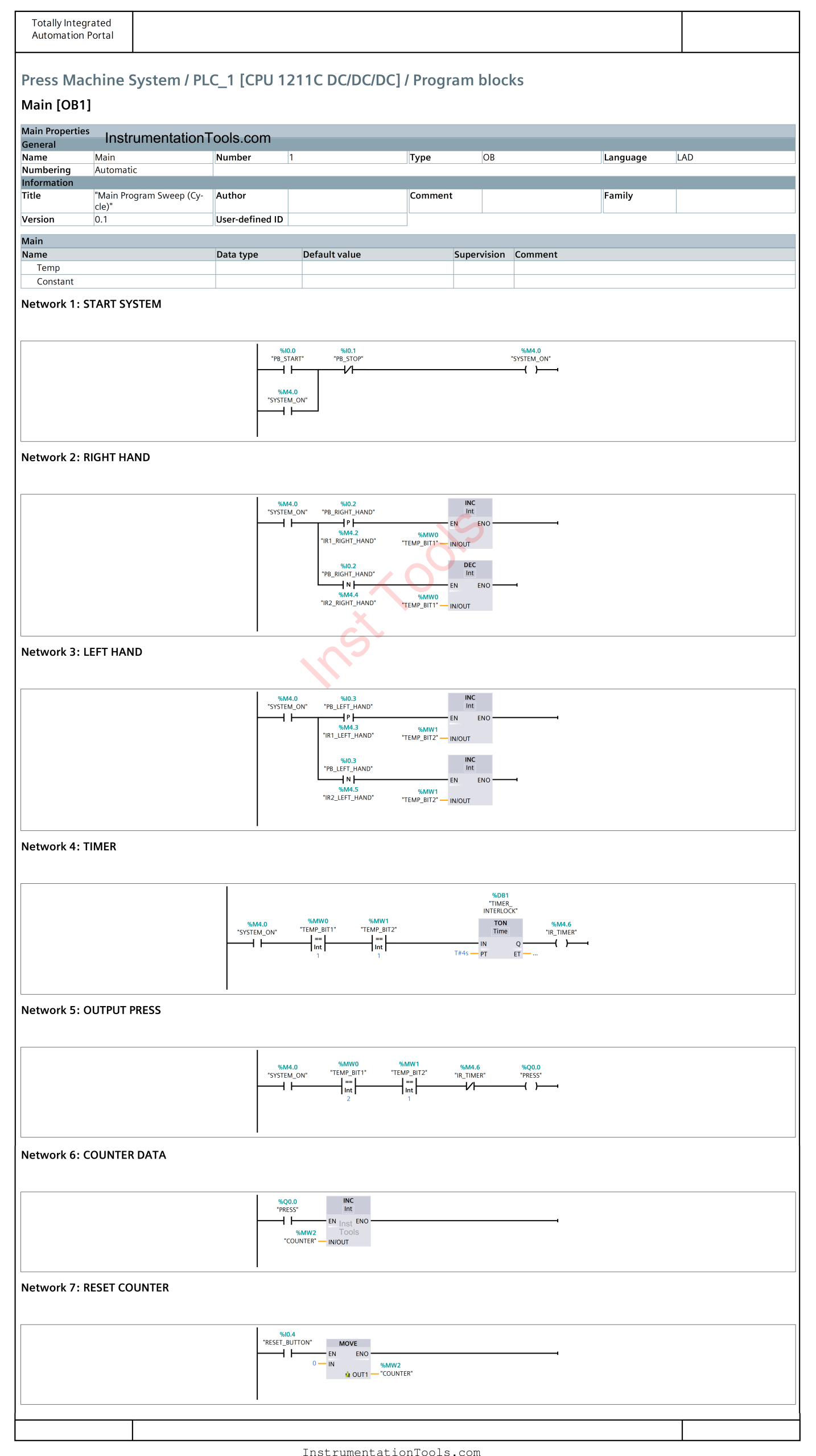
NETWORK 1 (SYSTEM ON)
In this network, if the PB_START (I0.0) button is pressed, the memory bit SYSTEM_ON (M4.0) will be in the HIGH state. The memory bit SYSTEM_ON (M4.0) will remain in the HIGH state even though the PB_START (I0.0) button has been released. Because it uses Latching.
If the PB_STOP (I0.1) button is pressed, the memory bit SYSTEM_ON (M4.0) will be in the LOW state.
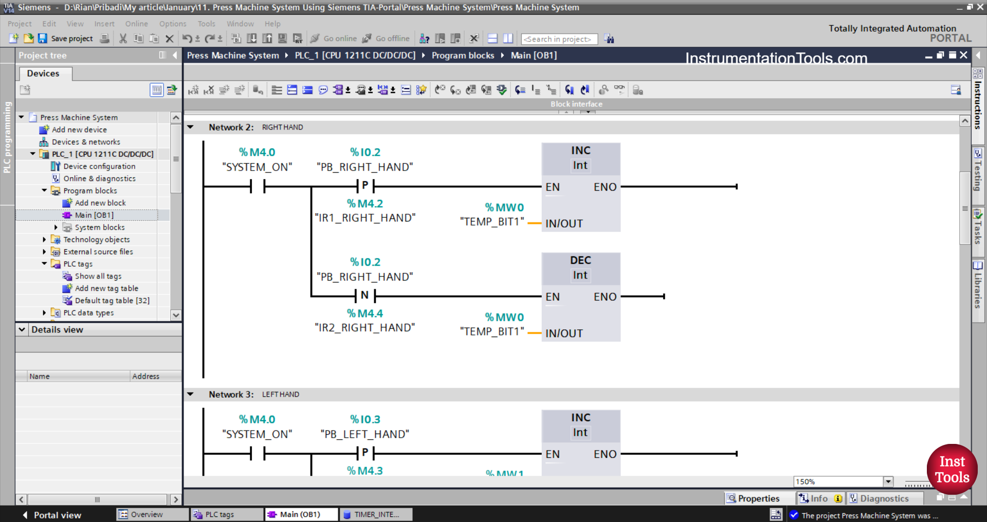
NETWORK 2 (RIGHT HAND)
In this Network, the value in the memory word TEMP_BIT1 (MW0) will increase by (+1) if the NO contact of the memory bit SYSTEM_ON (M4.0) is in the HIGH state and the PB_RIGHT_HAND (I0.2) button is pressed.
The value in memory word TEMP_BIT1 (MW0) will decrease by (-1) when the PB_RIGHT_HAND (I0.2) button is released.
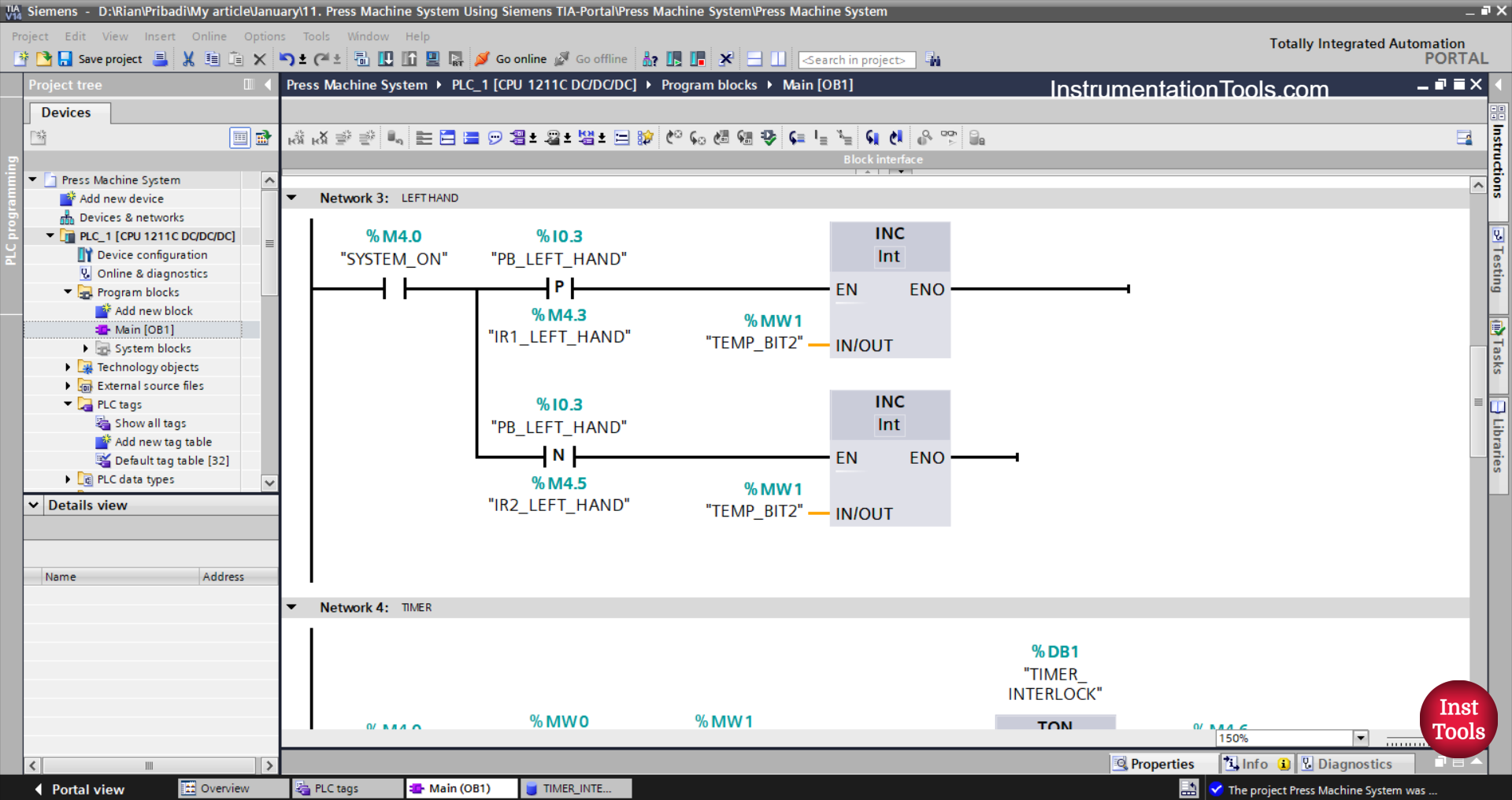
NETWORK 3 (LEFT HAND)
In this network, the value in the memory word TEMP_BIT2 (MW1) will increase by (+1) when the NO contact of the memory bit SYSTEM_ON (M4.0) becomes HIGH state and the PB_LEFT_HAND (I0.3) button is pressed.
The value in memory word TEMP_BIT2 (MW1) will decrease by (-1) when the PB_LEFT_HAND (I0.3) button is released.
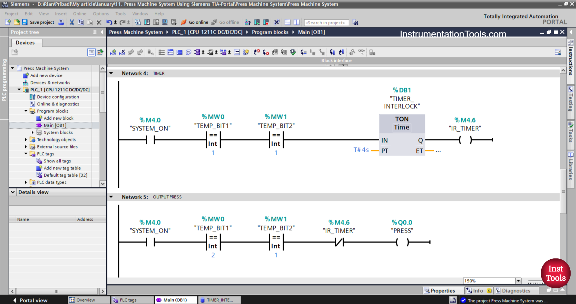
NETWORK 4 (TIMER)
The TIMER_INTERLOCK (DB1) timer will count up to 5 seconds When the NO contact of the memory bit SYSTEM_ON (M4.0) becomes in the HIGH state and the value in the memory words TEMP_BIT1 (MW0), TEMP_BIT2 (MW1) is Equal To “1”. After the TIMER_INTERLOCK (DB1) timer has finished counting, the memory bit IR_TIMER (M4.6) will be in the HIGH state.
NETWORK 5 (PRESS OUTPUT)
When the NO contact of the memory bit SYSTEM_ON (M4.0) becomes in the HIGH state and the value in the memory word TEMP_BIT1 (MW0), TEMP_BIT2 (MW1) is Equal To “1”, then the PRESS (Q0.0) output will be ON.
If the NC contact of the TIMER_INTERLOCK (DB1) timer is in the HIGH state, then the PRESS (Q0.0) output will be OFF.
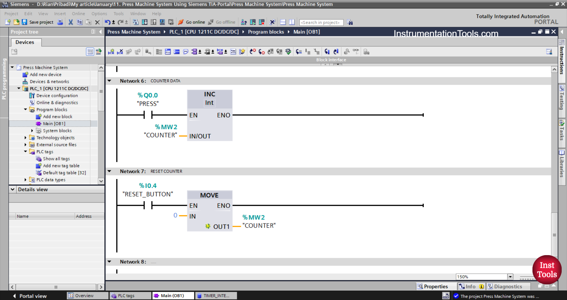
NETWORK 6 (COUNTER)
The value in the memory word COUNTER (MW2) will increase by (+1) when the NO contact of the PRESS (Q0.0) output is ON.
NETWORK 7 (RESET COUNTER)
The value in the memory word COUNTER (MW2) will be reset to zero “0” when the RESET_BUTTON (I0.4) button is pressed.
The Move instruction moves the zero value “0” to the memory word COUNTER (MW2).
Read Next:
- Mitsubishi PLC Based Sand Separator Logic
- Siemens PLC Manual and Automatic Garage Door
- Mitsubishi PLC Ladder Logic for Dual Tank Process
- How to Convert Integer to Float in Omron PLC?
- Siemens PLC Priority-Based Liquid Level Control