Practical Questions

Practical Process Control System Questions & Answers – 7

There is a problem somewhere in this liquid flow control system. The controller is in automatic mode, with a setpoint of 65%, yet the flow indicator and the flow controller both register 0.3%: (nearly) zero flow. A P&ID of the loop appears here:

liquid flow control system

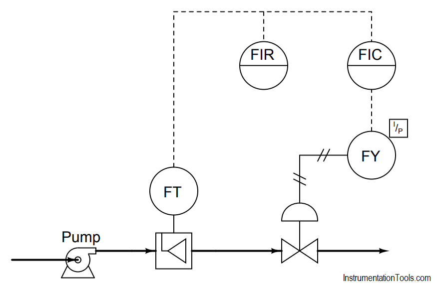
Explain how you would begin troubleshooting this system, and what possible faults could account for the controller not being able to maintain liquid flow at setpoint.

More Question

  1. Explain how you could divide this control system into distinct areas or zones which you may then begin to refer to when “dividing and conquering” the problem.

Answer :

One possible fault has to do with the control valve: perhaps something has happened to make it fail closed (loss of air supply, signal, etc.). Other possible problems include the following:

  • Pump not running (no source of fluid power to motivate flow)
  • Very poor controller tuning
  • Wrong controller action
  • Valve failed closed (loss of air supply, signal, etc.)
  • Transmitter failed, showing no flow when in fact there is

A good “first test” for troubleshooting the loop is to check the controller output: is it trying to open up the valve?

Share Your Answers via Comments

More Questions & Answers :
Practical Process Control System Questions & Answers – 1
Practical Process Control System Questions & Answers – 2
Practical Process Control System Questions & Answers – 3
Practical Process Control System Questions & Answers – 4
Practical Process Control System Questions & Answers – 5
Practical Process Control System Questions & Answers – 6
Practical Process Control System Questions & Answers – 7
Practical Process Control System Questions & Answers – 8
Practical Process Control System Questions & Answers – 9
Practical Process Control System Questions & Answers – 10
You've successfully subscribed !

View Comments

  • It would be nice to know how the pump is controled?
    Is it by a VFD? Is it binary (on and off).
    If the valve is closed, with out an interlock with the pump, the pump will dead head and go out on overload. With out the pump interlock, the FIC will be lost.
    This is not a very well designed loop.

Share

Recent Articles

  • PLC Tutorials

Example of Flip-Flop PLC Program for Lamps Application

Learn the example of flip-flop PLC program for lamps application using the ladder logic to…

3 days ago
  • PLC Tutorials

STAR DELTA Programming using PLC Controller

In this article, you will learn the STAR DELTA programming using PLC controller to start…

4 days ago
  • Instrumentation Design

Single and Three Phase Immersion Electrical Heaters Wiring Circuits

Lube oil consoles of rotary equipment packages in industrial process plants are usually equipped with…

22 hours ago
  • Instrumentation Design

Immersion Heaters in Lube Oil Consoles

Rotating equipment packages such as pumps, compressors, turbines need the lube oil consoles for their…

3 days ago
  • PLC Tutorials

How to Blink Lights in Ladder Logic?

This article explains how to blink lights in ladder logic with a detailed explanation video…

3 weeks ago
  • PLC Tutorials

From Boolean Algebra to PLC Logic

In this article, a simple example will teach you the conversion from Boolean algebra to…

1 month ago