Air Consumption and Air Flow
The difference between air consumption and flow rate can sometimes be confusing since both are specified using the same units.
Air Consumption is defined as the amount of free air (compressed volume expanded to atmospheric pressure) used by a system during a given time period whilst Air Flow is the rate at which the air is consumed, i.e. a system which operates once every minute and consumes 100 litres of free air has a consumption of 100 ln/min, however, if the same system only takes 1 second to operate and is at rest for the remaining 59, the flow of air into the system is at the rate of 6000 ln/min.
Note : ln represents normal litres
It is flow rate that is of prime importance when considering the size of control system components required to power a cylinder at a given speed.
System Sizing
Traditionally, valves have been specified by matching their port size to that of the cylinder in use. Also, tube fittings and tube are often selected by appearance rather than functionality in mind. This method is however, highly speculative and provides no theoretical proof that the correct components have been chosen. Instead, it is necessary to use the required flow rate, the working pressure and the acceptable pressure drop across the system, to establish an accurate value for the coefficient of flow, measured in Cv or kv.
A Cv of one is equal to a flow rate of one US gallon of water per minute, with a pressure drop of one psi. A kv of one is equal to a flow rate of one litre of water per minute, with a pressure drop of one bar.
Most manufacturers now state either a Cv or kv figure for their components. In some instances, however, this may be shown by a value labelled S, which represents the flow section in mm2 of an orifice in a diaphragm, creating a similar relationship between pressure and flow.
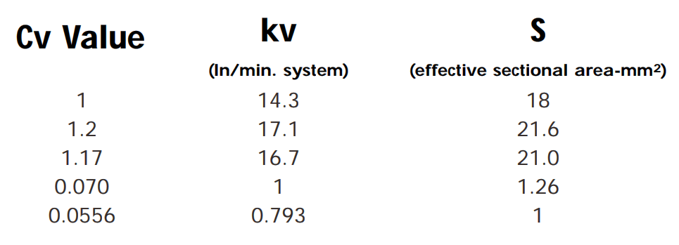
Note :S values can be converted to Cv by dividing by 18 (approx.) and to kv by dividing by 14.3
Cv, “Coefficient of velocity, Flow factor” differs from country to country and also from industry to industry. Because of the slight difference in definition, exact conversion cannot be made, however, SMC uses the table shown below.
For each case, a formula is available to calculate the air flow under given conditions of pressure.
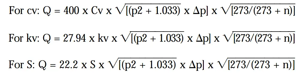
Cv, kv = Coefficients of flow
S = Equivalent flow section in mm2
Q = The standard flow rate of the valve in litres/min
p2 = Outlet pressure required to drive the cylinder
Dp = Permissible pressure drop
n = Air temperature in °C
At normal working temperatures, the calculation:
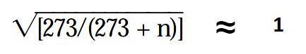
So that this part of the formulae can be ignored.
Example 3: Consider the problem outlined in example 1.
The problem can be expanded to include an operating time, i.e., it has been determined that the 150 kg load must be moved a distance of 200 mm in 1 second.
We calculated a theoretical piston diameter of 60.05 mm and recognised that, since a cylinder of this bore did not exist, we would select the next standard bore size, i.e. 63mm.
It is necessary to first calculate the minimum system operating pressure.
Remember:- Thrust = Pressure x Area x Efficiency
therefore, Pressure = Thrust / (Area x Efficiency)
In our example:
P = 150 x 4 / ( p x 6.3 2 x 0.9) P = 5.35 kgf/cm2
Since our previous calculations assumed a decaying pressure of 1.5 kgf/cm2 on the side of the piston open to atmosphere, (which must be compensated for in the working pressure ), the actual pressure required to move the load will be 5.35 + 1.5 = 6.85 kgf/cm2
Since we have 7.3 kgf/cm2 of air pressure available, it follows that we can tolerate a system pressure drop (Δp) of 7.3 – 6.85 = 0.45 kgf/cm2.
The system air consumption can be calculated by multiplying the piston area by the distance it has to move in this case:
π x 6.32 cm x 20 cm / 4 = 624 cm3 or 0.624 litres.
This volume will be occupied by air at 6.85 kgf/cm2 which, using Boyles Law (P1V1 = P2V2) gives:
Note : Pressures used in Boyles Law must be stated as absolute not gauge
(6.85 + 1) x 0.624 = 1 x V2
V2 = 7.85 x 0.624/ 1
therefore, air consumption = 4.9 ln/stroke
This amount of air is consumed each time the system operates (out strokes of the cylinder). Since the time taken we know has to be 1 second, the flow rate could be expressed as 4.9 ln/s.
In order that this value can be used in our formula (Q), it must be expressed in ln/min.
Q = 4.9 x 60 = 294 1n/min
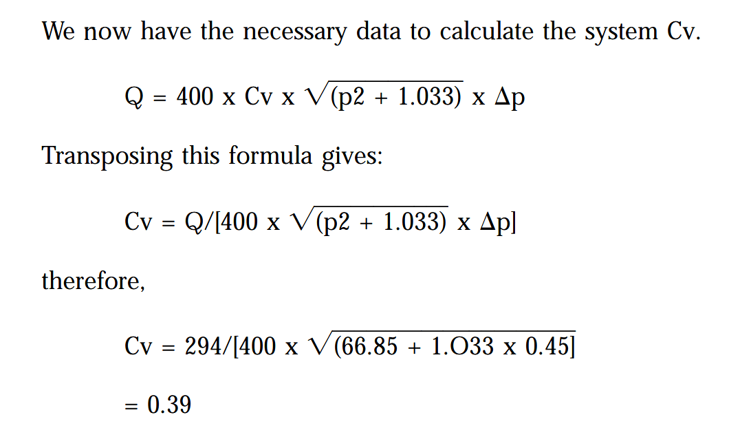
Applying System Cv to Component Selection
Individual components within a system each have a Cv value, i.e. valves, tube fittings, and tubing.
The composite Cv when components Cv1, Cv2, etc are connected in sequence is calculated by :

In practical terms, it has been found economically sound to allow 50% of system pressure drop to exist in the tube and tube fittings; the other 50% being attributed to the valve system, e.g., if system Cv = 1
1/12 = 1/Cv12 + 1/Cv22
where Cv1 & Cv2 have the same value (50:50 split).
1 = 2/Cv2
so, Cv2 = 2
hence Cv = √2 = 1.4
We can, therefore, assume that for a system Cv of 0.39 (as per our example), a good start point is to assume a valve Cv of 0.39 x 1.4 = 0.55.
From manufacturer’s literature, a valve of suitable function, with a minimum Cv of 0.55 can be selected.
Having selected the valve, its port size will determine the largest tube size that can be used (dependent on the range of tube fittings available).
Calculation of the exact Cv for tube and fittings can then be be made.
In our example we find that a valve having a port size of 1/8” BSP is suitable.
With this size of port, tube fittings determine that the maximum available tube size is 10 mm O/D.
If our system consists of 2 metres of 10 mm tube, three 10mm O/D x 1/8” BSP straight adaptors and one 10mm O/D x 3/8” BSP elbow adaptor; tube and fittings Cv would be:
10mm O/D tube x 2m: Cv = 1.47**
10 mm O/D x 1/8” BSP straight adaptor: S value = 41.5 or Cv = 2.3*
10mm O/D x 3/8” BSP elbow adaptor: S value = 35.2 or Cv = 1.95*
*from manufacturer’s literature. **Cv of nylon tube is calculated by the formula:
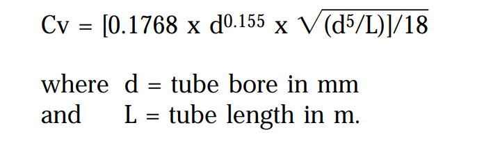
The above formula can be simplified for a selection of popular tube O/D’s:
Continuing our example:
1/Cv2 = 1/1.472 + 3/2.32 + 1/1.952
1/Cv2 = 0.46 + 0.57 + 0.26 = 1.29
therefore, Cv= √(1/1.29) = 0.88
Since we know that the system Cv has to be 0.39 as per our example:-
A valve can now be selected having Cv minimum of 0.43 providing it can be used with ø10 mm tube.
Also Read : Pneumatic Valves and Cylinders Sizing – Part 1
Source : smc.eu