Question 1:
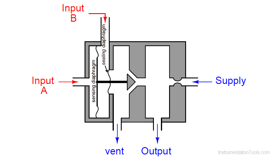
What is the response of this pneumatic relay to increasing pressure on each of its inputs? Does the output pressure increase as input A’s pressure increases? What happens when input B’s pressure increases?
Note that both the sensing and sealing diaphragms are welded to the pilot rod, forming leak-proof and frictionless seals between chambers:
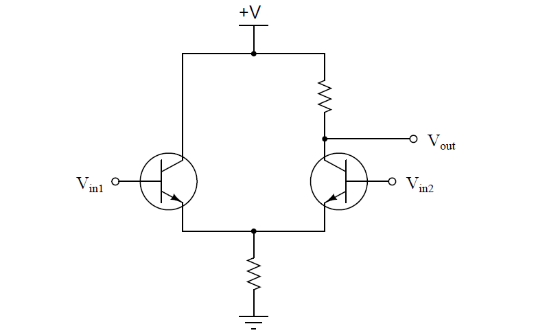
Can you think of an electronic circuit or device that acts in an analogous manner?
Answer:
A bit of explanation might be in order for the two diaphragms. The larger diaphragm is called the sensing diaphragm, while the smaller diaphragm is called the sealing diaphragm.
The purpose of the sealing diaphragm is to prevent air pressure at input B from leaking out into the vented chamber just to the left of the wedge-shaped pilot plug.
This sealing diaphragm is made small enough that its contribution to force on the stem is negligible. Only the sensing diaphragm is large enough to have any consequence upon the pilot valve’s action.
This is an equivalent electronic circuit:
Question 2:
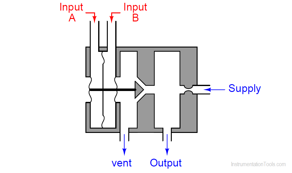
Also, explain why the following relay design is better, using two sealing diaphragms instead of just one. A hint is to consider the common-mode rejection capacity of each relay design.
Once again, each of the metal diaphragms is welded to the rod to form leak-proof and frictionless seals:
Question 3:
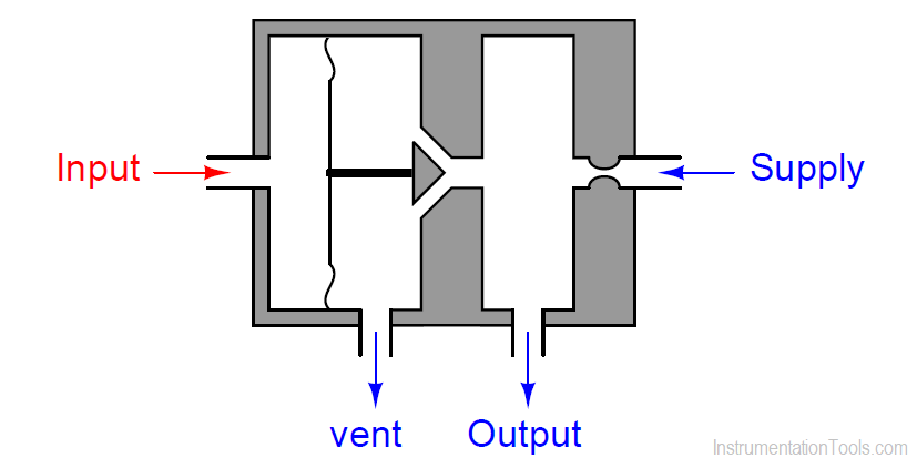
Does the output pressure of this relay increase with increasing input pressure, or decrease with increasing input pressure?
In other words, is it a direct-acting or reverse acting type of relay?
Share your answers with us through below comments section.
Read Next:
- Relays in Ladder Logic
- Diaphragm Pressure Sensor
- Solid State Relays
- What is a Interposing Relay?
- Analyze the Relay Circuit
Credits: Tony R. Kuphaldt
